Automated oil tube outside-well cutting device

A cutting device, cutting device technology, applied in the direction of pipe shearing device, shearing device, accessory device of shearing machine, etc., can solve the problems of low production efficiency, high labor intensity, etc. The effect of strong flexibility

Inactive Publication Date: 2017-09-19
中国石油天然气股份有限公司勘探开发研究院
View PDF8 Cites 8 Cited by
  • Summary
  • Abstract
  • Description
  • Claims
  • Application Information

AI Technical Summary

Problems solved by technology

At present, the cutting of the oil pipe mainly relies on manual operation, the production efficiency is low, and the manual labor intensity is high

Method used


Image

  • Automated oil tube outside-well cutting device

Examples


Embodiment Construction

[0020] The present invention will be further described in detail below through the specific examples, the following examples are only descriptive, not restrictive, and cannot limit the protection scope of the present invention with this.

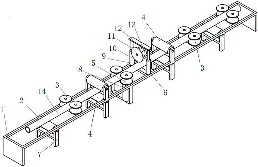
[0021] Such as figure 1 As shown, the automatic tubing out-hole cutting device of the present invention includes a frame 1 , and a transmission roller 2 , a horizontal righting roller 3 , a longitudinal righting roller 4 , a driving roller 5 , and a cutting device 6 arranged on the frame 1 . Wherein the frame 1 is a long rectangular frame, the cutting device 6 is arranged in the middle of the frame 1, and the feeding side of the cutting device 6 is successively provided with a driving roller 5, a vertical righting roller 4, a horizontal righting roller 3, a transmission roller 2, and the discharging side Vertical righting roller 4, horizontal righting roller 3, transmission roller 2 are set.

[0022] The frame 1 includes a conveying plane a...


PUM


Abstract

The invention relates to an automated oil tube outside-well cutting device. The automated oil tube outside-well cutting device comprises a rack, conveying rollers, transverse righting rollers, longitudinal righting rollers, a driving roller, a cutting device and a PLC controller, wherein the conveying rollers, the transverse righting rollers, the longitudinal righting rollers, the driving roller and the cutting device are arranged on the rack, and the rolling tangent planes of the conveying rollers and the driving roller constitute a conveying plane together; and the cutting device is arranged in the middle of the rack, the driving roller, the first longitudinal righting roller, the first transverse righting roller and the first conveying roller are arranged at the feeding side of the cutting device sequentially, and the second longitudinal righting roller, the second transverse driving rollers and the second conveying roller are arranged at the discharging side of the cutting device sequentially. According to the automated oil tube outside-well cutting device, the rolling tangent planes of the conveying rollers and the driving roller constitute the conveying plane together, so that the functions of supporting an oil tube and reducing conveying friction are achieved; and meanwhile the transverse righting rollers and the longitudinal righting rollers limit the upper, lower, left and right positions of the oil tube in the rolling advancing process, so that the function of righting the oil tube is achieved.

Description

technical field [0001] The invention relates to an auxiliary equipment for oil recovery, in particular to an automatic oil pipe outside well cutting device used for cutting the scrap oil pipe during the repair process. Background technique [0002] The oil pipeline is the pipeline that transports crude oil and natural gas from the oil and gas layer to the surface after the drilling is completed, and plays a vital role in the oil recovery and production of the oil field. Usually, the outer diameter of the tubing is Φ48, Φ60, Φ73, Φ88mm, and the total length ranges from 6-12m. At present, failures such as corrosion and fracture of oil pipes in domestic oilfield pumping wells are very common, so the re-repair of scrap oil pipes is of great significance. When the oil pipe is repaired, it is usually necessary to cut off the damaged part of the oil pipe. At present, the cutting of oil pipes mainly relies on manual operation, which has low production efficiency and high labor int...

Claims


Application Information

Patent Timeline
Patent Type & Authority Applications(China)
IPC IPC(8): B23D21/00B23D19/00B23D33/02
CPCB23D21/00B23D19/00B23D33/02
Inventor 姚尚林窦宏恩邹存友
Owner 中国石油天然气股份有限公司勘探开发研究院
Why Eureka
Try Eureka