Non-uniform disturbance electrical sparkle micro hole machining device

A processing device and non-uniform technology, which is applied in the field of metal processing and EDM micro-hole processing, can solve the problems such as the difficulty of removing electro-corrosion products, achieve a large flow of working fluid, prevent congestion of electro-corrosion products, and prevent non-uniform side walls The effect of discharge

Active Publication Date: 2017-09-19
DALIAN JIAOTONG UNIVERSITY
View PDF13 Cites 4 Cited by
  • Summary
  • Abstract
  • Description
  • Claims
  • Application Information

AI Technical Summary

Problems solved by technology

[0003] The purpose of the present invention is to provide a device that can effectively eliminate the electro-corrosion products of electric discharge machining, solve the

Method used


Image

  • Non-uniform disturbance electrical sparkle micro hole machining device
  • Non-uniform disturbance electrical sparkle micro hole machining device
  • Non-uniform disturbance electrical sparkle micro hole machining device

Examples


Embodiment Construction

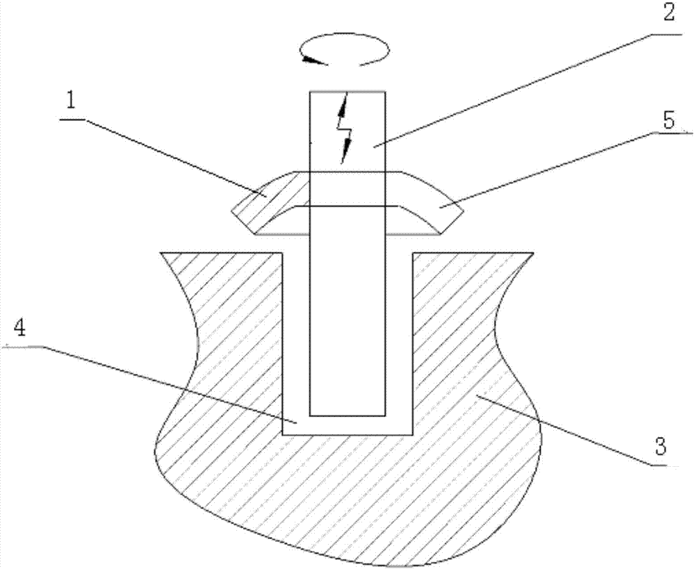
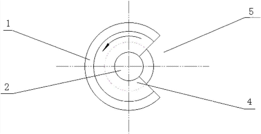
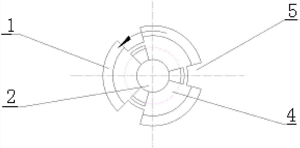
[0023] Attached below image 3 And the specific embodiment will further illustrate the present invention:

[0024] The non-uniform disturbance electric discharge micro-hole machining device includes electric discharge machining equipment. The tool electrode 2 of the electric discharge machining equipment has a compound motion of rotation and vibration during the machining process. The tool electrode 2 is equipped with a non-uniform disturbance actuator 1. The non-uniform disturbance actuator 1 is a disc with notches. There are more than one notch. The central hole of the disk is installed on the tool electrode 2 through a rubber ring, and is located above the workpiece 3 to be processed. The gap between the edge of the non-uniform disturbance actuator 1 and the upper surface of the workpiece is m, and 0mm≤m≥the amplitude of the tool electrode 2.

[0025] The working process of the present invention is: in the downward stage of the vibration of the tool electrode 2, the tool e...


PUM


Abstract

A non-uniform disturbance electrical sparkle micro hole machining device comprises electrical sparkle machining equipment. A tool electrode of the electrical sparkle machining equipment is provided with a disk-type non-uniform disturbance execution piece with a notch, a disk center hole is arranged on the tool electrode through a rubber ring and is located above a workpiece to be machined, the gap between the disk center hole and the upper surface of the workpiece is m, and m is larger than or equal to 0 mm and also larger than or equal to the amplitude of the tool electrode. The non-uniform disturbance electrical sparkle micro hole machining device has the beneficial effects that disturbance directly acts on the vertical direction of a gap flow field and can effectively arrive at the bottom of the machining gap; electrolytic corrosion products are discharged without dead corners, and fluid motion is accelerated; the discharged electrolytic corrosion products can be prevented from flowing back, and one-directional discharging of the electrolytic corrosion products is achieved; the electrolytic corrosion products can be discharged through multiple channels, and electrolytic corrosion product crowding and non-uniform side wall discharging are prevented; and the flowing amount of working liquid is large.

Description

technical field [0001] The invention belongs to the technical field of metal processing, in particular to the field of electric discharge micro hole processing. Background technique [0002] In the prior art, there are two methods for micro-hole machining: one method is the traditional drilling method, which has certain advantages in terms of economy and precision. The chip flute is small and the chip removal is not smooth, so it is not suitable for processing difficult-to-machine materials; another method is electric discharge machining. Difficult to exclude, it is difficult to maintain processing stability, affect the processing depth of small holes, and even processing is difficult. To this end, it is a technical problem to be solved to study a device that can effectively eliminate the electro-corrosion products and improve the depth-to-diameter ratio of micro-hole processing. Contents of the invention [0003] The purpose of the present invention is to provide a devi...

Claims


Application Information

Patent Timeline
IPC IPC(8): B23H9/14
CPCB23H9/14Y02P70/10
Inventor 张生芳张文超刘宇马付建沙智华阎长罡宿崇栾安科
Owner DALIAN JIAOTONG UNIVERSITY
Why Eureka
Try Eureka