Gas-liquid substitution and vacuuming personnel protection cabin

A protection cabin and vacuum pumping technology, which is applied in the field of protection cabin, can solve the problems that it cannot be used in a manned space, the life safety of personnel is threatened, and the gas purity is difficult to guarantee, so as to reduce the waste of protection period, simple structure and low consumption. Effect

Active Publication Date: 2018-11-13
CHINA SHIP SCIENTIFIC RESEARCH CENTER (THE 702 INSTITUTE OF CHINA SHIPBUILDING INDUSTRY CORPORATION)
View PDF8 Cites 0 Cited by
  • Summary
  • Abstract
  • Description
  • Claims
  • Application Information

AI Technical Summary

Problems solved by technology

In order to ensure the purity of the protective gas in the enclosed space, the current method is to vacuumize and then fill the protective gas, but the vacuum environment poses a threat to the safety of personnel, so it cannot be used in a space with people; in addition, there is a direct substitution method, By setting up the conversion facility, the personnel directly physically replace the air in the conversion facility while wearing the breathing apparatus
The direct substitution method has the following disadvantages: 1. A large amount of protective gas is consumed; 2. It is difficult to guarantee the purity of the final gas; 3. Different gases are mixed with each other in the inflation substitution, and the process controllability is poor

Method used


Image

  • Gas-liquid substitution and vacuuming personnel protection cabin
  • Gas-liquid substitution and vacuuming personnel protection cabin

Examples


Embodiment Construction

[0019] Specific embodiments of the present invention will be described below.

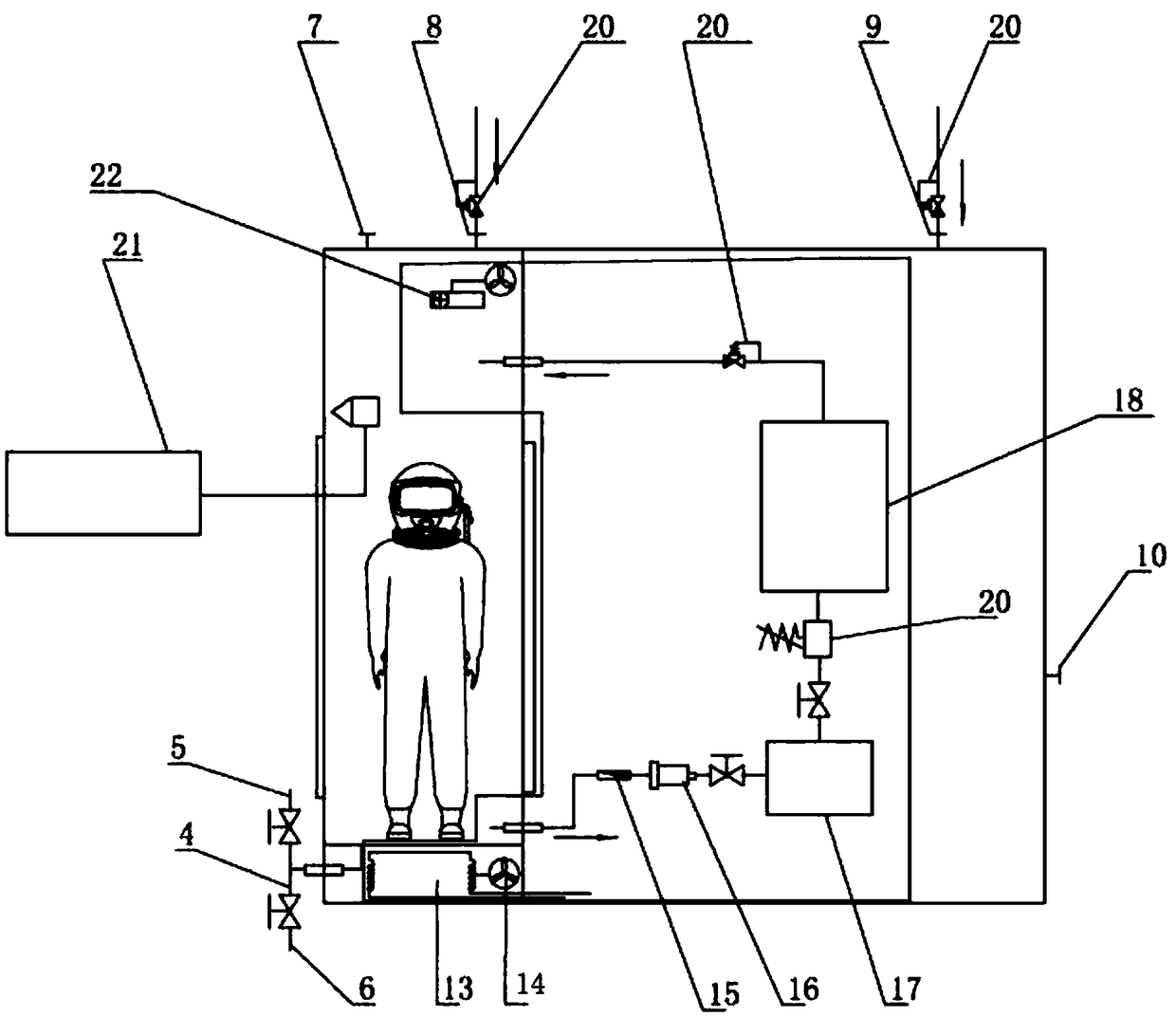
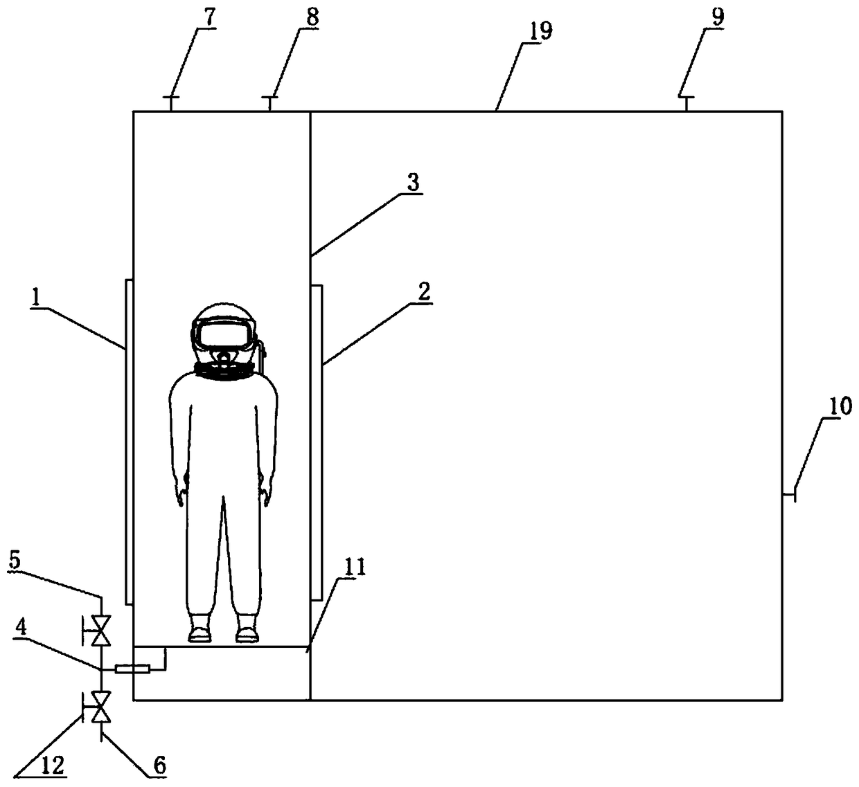
[0020] Such as figure 1 As shown, the gas-liquid substitution and vacuuming personnel protection cabin includes a vacuuming cabin 19, a protective cabin main body 3 is set in the vacuuming cabin 19, and a vacuuming cabin for entering the protective cabin main body 3 is arranged on one side of the vacuuming cabin 19 The airtight door 1 is provided with a protective cabin airtight door 2 on one side of the protective cabin main body 3; the air exhaust port 7 and the first filling protective air port 8 are arranged on the top of the protective cabin main body 3, and are respectively set on the vacuum chamber 19 The second filling and protection gas port 9 and the vacuum chamber pumping port 10; also include the injection and discharge pipeline tee 4, the first end of the injection and discharge pipeline tee 4 is connected to the liquid injection port 4, and the injection and discharge pipeline tee 4 ...


PUM


Abstract

The invention relates to a gas-liquid replacement vacuumizing personnel protection cabin which comprises a vacuumizing cabin. A protection cabin body is arranged in the vacuumizing cabin. A vacuumizing cabin airtight door is arranged on one side of the vacuumizing cabin, and a protection cabin airtight door is arranged on one side of the protection cabin body. An air exhaust opening and a first protection gas filling opening are formed in the top of the protection cabin body, and a second protection gas filling opening and a vacuumizing cabin vacuumizing opening are formed in the vacuumizing cabin. A liquid injection and drainage pipeline tee joint is further included, the first end of the liquid injection and drainage pipeline tee joint is connected with a liquid injection opening, the second end of the liquid injection and drainage pipeline tee joint is connected with a liquid drainage opening, and the third end of the liquid injection and drainage pipeline tee joint is introduced into the protection cabin body. According to the gas-liquid replacement vacuumizing personnel protection cabin, the vacuum environment is isolated from the environment where working personnel are located, and the risks of the working personnel during vacuumizing are avoided. Gas injection and liquid drainage are achieved in the protection cabin body, and therefore air can be fast and effectively discharged, components in the air are prevented from being mixed with protection gas, the purity of the protection gas is greatly guaranteed, and protection period waste of the gas replacement link is reduced.

Description

technical field [0001] The invention relates to the field of protective cabins, in particular to a protective cabin for gas-liquid substitution and vacuuming personnel. Background technique [0002] Inert gas is mostly used as shielding gas in welding operations. For large workpieces and complex welds, the overall protection of inert gas is of higher quality than partial protection. Certain special welding operations must be performed in a closed space filled with high-purity inert gas. In order to ensure the purity of the protective gas in the enclosed space, the current method is to vacuumize and then fill the protective gas, but the vacuum environment poses a threat to the safety of personnel, so it cannot be used in a space with people; in addition, there is a direct substitution method, By setting up the conversion facility, the personnel directly physically replace the air in the conversion facility while wearing the breathing apparatus. The direct substitution method...

Claims


Application Information

Patent Timeline
Patent Type & Authority Patents(China)
IPC IPC(8): B23K37/00E04H5/02
CPCB23K37/00B23K37/006E04H5/02
Inventor 徐蒙王博赵远辉徐仁超
Owner CHINA SHIP SCIENTIFIC RESEARCH CENTER (THE 702 INSTITUTE OF CHINA SHIPBUILDING INDUSTRY CORPORATION)
Why Eureka
Try Eureka