a punching device

A technology of punching device and dimples, which is applied in the field of fabric processing, can solve the problems of great significance, inability to accurately position the lower mold, errors and other problems of luggage companies, and achieve increased profit margins, fast work efficiency and good molding effects Effect

Active Publication Date: 2019-03-22
VITAL INT ELEVATORING EQUIP
View PDF10 Cites 2 Cited by
  • Summary
  • Abstract
  • Description
  • Claims
  • Application Information

AI Technical Summary

Problems solved by technology

In fact, the operator cannot accurately locate the position of the lower mold when punching holes, and the processed holes have certain errors. How to design a device to perform accurate punching operations before fabric wrapping is of great significance to luggage companies.

Method used


Image

  • a punching device
  • a punching device
  • a punching device

Examples


Embodiment Construction

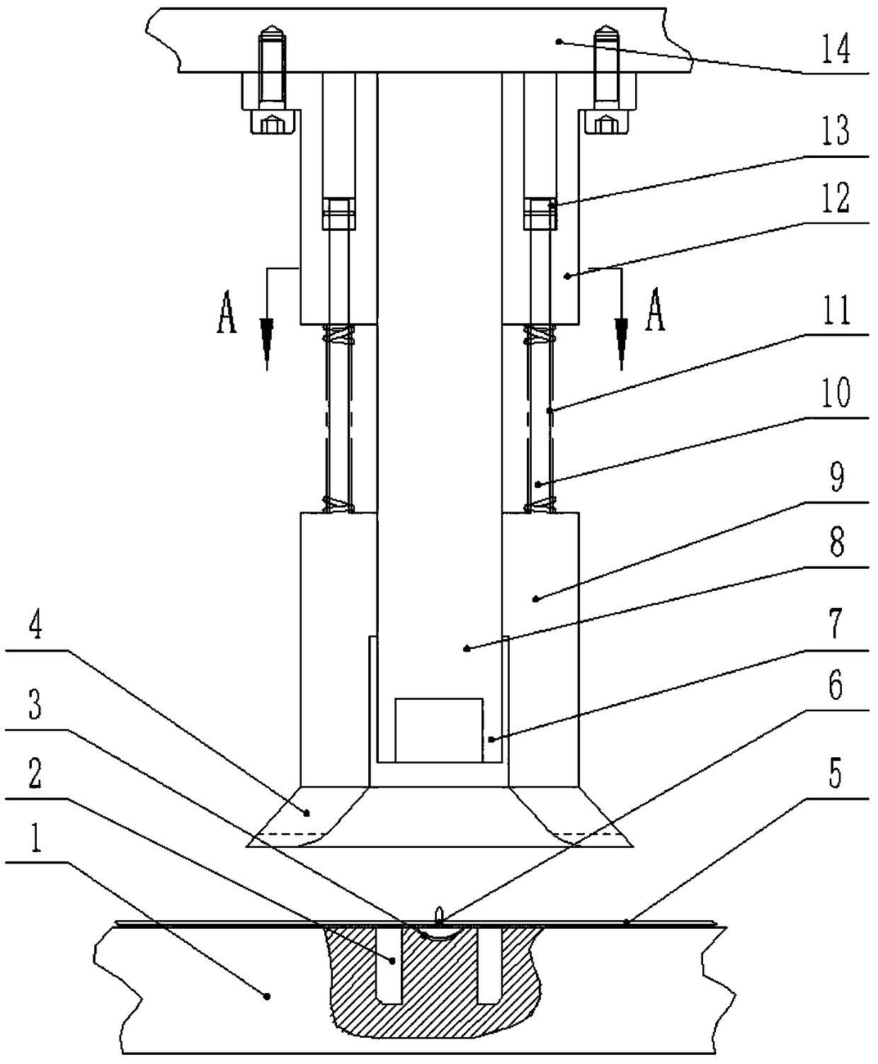
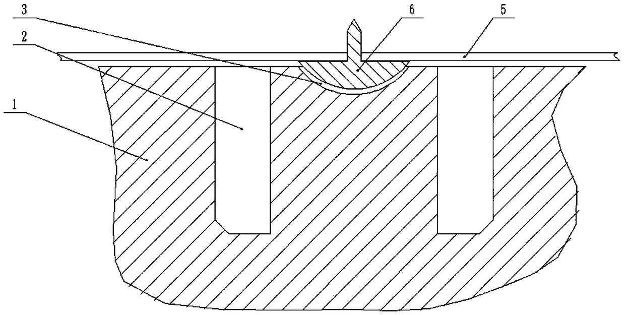
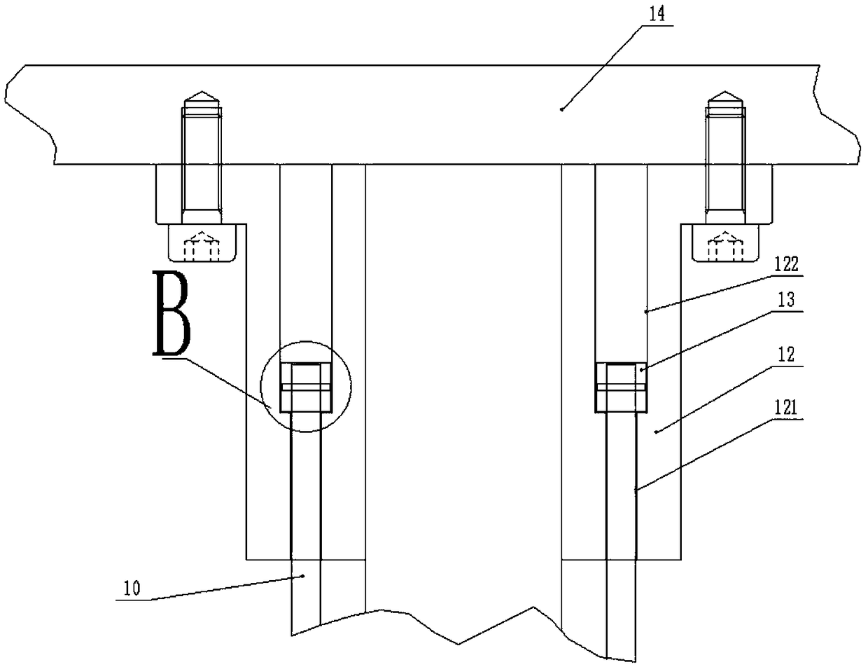
[0026] As shown in the figure, a punching device according to an embodiment of the present invention includes: figure 2 As shown, the workbench 1 is processed with an annular groove 2 and a pit 3, the pit 3 is located in the middle of the annular groove 2, and the shape of the pit 3 is consistent with the shape of the bottom 61 of the tack 6; as figure 1 As shown, the lifting platform 14 is located above the workbench 1, and the lifting platform 14 is driven by the power mechanism to move up and down, as figure 1 , image 3 As shown, the lower surface of the lifting table 14 is concentrically installed with a central shaft 8 and a fixed sleeve 12, the position of the central shaft 8 corresponds to the pit 3, the lower end of the central shaft 8 is fixed to the cutter head 7, and the cutter head 7 is matched with the annular groove 2, fixed Processing through hole 121, through hole I122 in cover 12, as Figure 4 As shown, the size of the through hole I122 is larger than that...


PUM


Abstract

The invention relates to a perforating device which comprises a worktable, wherein an annular groove and a pit are processed in the worktable; the pit is located in the middle position of the annular groove; a lifting table is positioned right above the annular groove; a central shaft and a fixed cover are concentrically mounted on the lower surface of the lifting table; a tool bit is fixed on the lower end of the central shaft; a through hole and a through hole I are processed in the fixed cover; a movable cover is mounted below the fixed cover out of the central shaft; the upper end of the movable cover is fixedly connected to a guide rod; the guide rod extends into the through hole I and is locked by a limiting block; a pressure spring is also arranged on the guide rod; an elastic ring is fixed at the lower end of the movable cover; a large-headed nail punctures a perforated position of a shell fabric; when the perforated position is moved under the tool bit, the large-headed nail sinks into the pit to be positioned; when the lifting table moves downward, the elastic ring is in contact with the shell fabric first and unfolds the shell fabric; and under shrinkage of the pressure spring, the tool bit enters the annular groove to perforate the shell fabric. The device is simple in structure, finishes the perforating operation of the shell fabric in advance, and is quite practical.

Description

technical field [0001] The invention relates to the field of fabric processing, in particular to a punching device. Background technique [0002] Suitcases, handbags and other bags are wrapped with fabrics. Since handles, universal wheels and other components need to be installed on the bags, it is necessary to punch holes in multiple positions on the fabric. The current processing method is generally after the fabric wrapping is completed. Relying on the matching mold to manually punch holes, this method is labor-intensive and low-efficiency, and because the fabric has actually been formed, the holes processed on the formed fabric are not beautiful. Because existing punching device all is to process lower die on the desktop, i.e. groove, impacts by upper die above, forms relative shearing, forming hole. In fact, the operator cannot accurately locate the position of the lower mold when punching holes, and the processed holes have certain errors. How to design a device to pe...

Claims


Application Information

Patent Timeline
Patent Type & Authority Patents(China)
IPC IPC(8): B26F1/16B26D7/01D06H7/00
CPCB26D7/015B26F1/16D06H7/00
Inventor 龚雅萍
Owner VITAL INT ELEVATORING EQUIP
Why Eureka
Try Eureka