Tool platform suitable for positioning of cast-in-place pile reinforcement cage and guide pipe

A technology for positioning platform and reinforcement cage, applied in sheet pile wall, infrastructure engineering, construction and other directions, can solve the problems of small operation surface, many sections of reinforcement cage of pile body, increased work intensity of operators, etc., so as to improve operation efficiency. Effect

Active Publication Date: 2017-09-19
CCCC SHEC FOURTH ENG +1
View PDF3 Cites 7 Cited by
  • Summary
  • Abstract
  • Description
  • Claims
  • Application Information

AI Technical Summary

Problems solved by technology

[0002] In the prior art, during the construction of cast-in-situ piles, the steel cage is often positioned by inserting section steel to support the top of the steel casing during the lengthening process of the steel cage. When inserting and pulling out the section steel, the physical strength of the operator is greatly consumed, and it is also There are certain safety risks; with the development of civil engineering technology, there are more and more large-diameter deep and long piles, which makes the reinforcement cage of the pile body heavier and more segmented, and the gap between the vertical main bars is also smaller. Smaller and smaller, resulting in the large size of the steel can not penetrate the gap between the vertical main reinforcement, the strength of the small size of the steel can not meet the force requirements, and the increase in the number of sections will double the work intensity of the operator
In order to solve this kind of problem, the process of positioning the steel cage by adopting the piggyback method has begun to be applied, but the piggyback plate, the key structure of the piggyback process, is still supported on the top of the steel casing, and there is a risk of the steel casing sinking suddenly. The operating area that the panel can provide is very small, and there are potential safety hazards in construction
When pouring concrete, the conduit support platform is often hoisted and placed directly on the top of the steel casing, which poses a risk of overturning and poses a great safety hazard

Method used


Image

  • Tool platform suitable for positioning of cast-in-place pile reinforcement cage and guide pipe
  • Tool platform suitable for positioning of cast-in-place pile reinforcement cage and guide pipe
  • Tool platform suitable for positioning of cast-in-place pile reinforcement cage and guide pipe

Examples


Embodiment Construction

[0026] The present invention will be further described below in combination with specific embodiments and accompanying drawings.

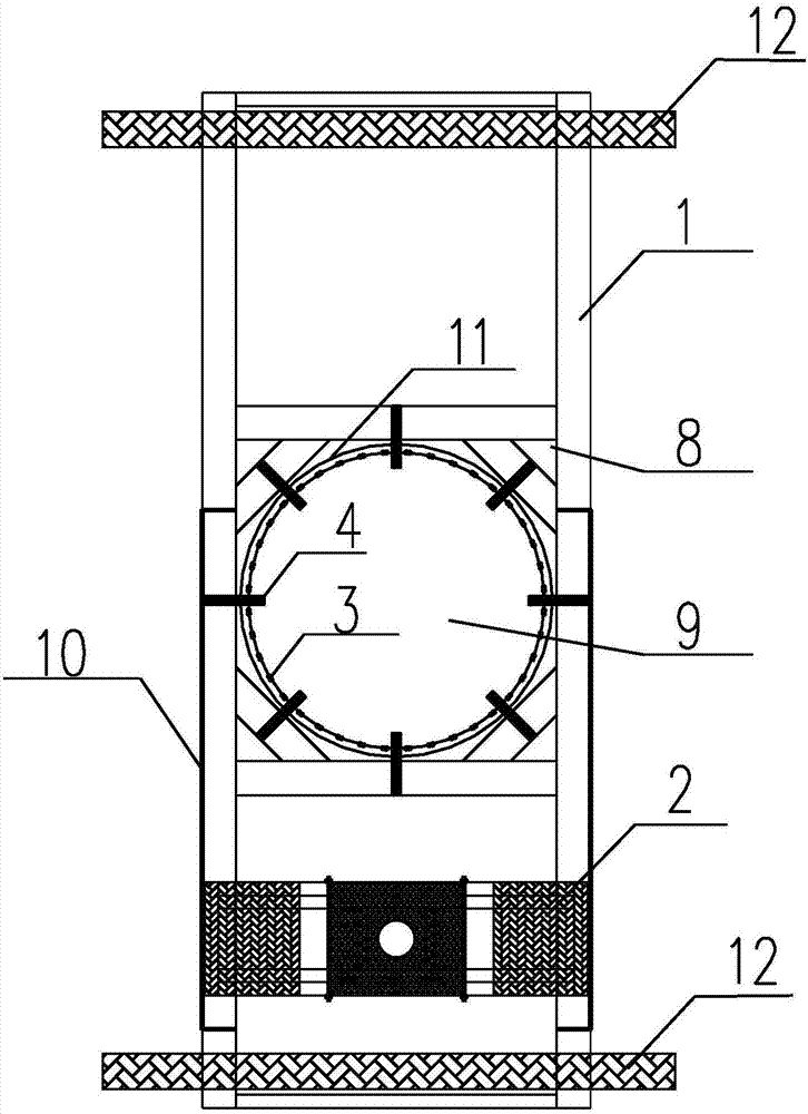
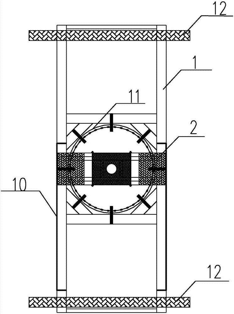
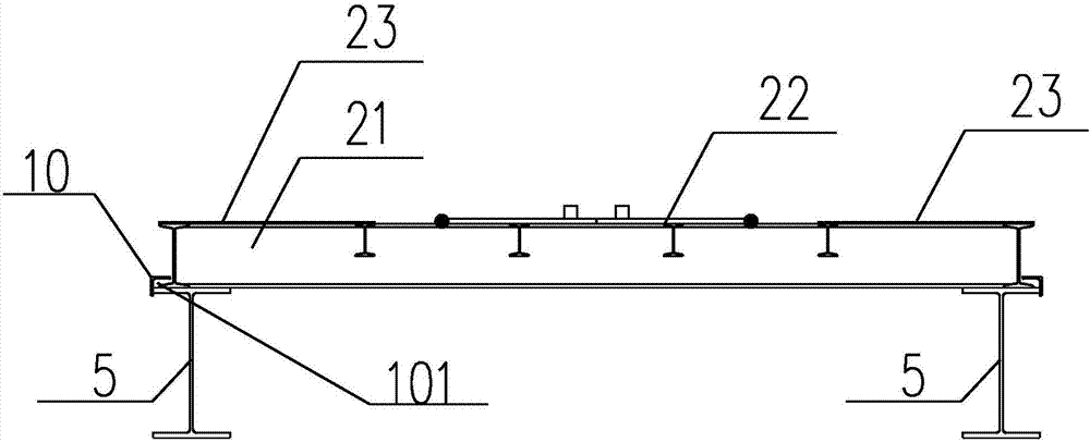
[0027] refer to Figure 1-7 As shown, a tool platform suitable for the positioning of cast-in-situ pile reinforcement cages and conduits includes a reinforcement cage positioning platform 1 and a conduit positioning platform 2. The reinforcement cage positioning platform 1 includes a frame main body and is arranged on the frame main body to support the steel bars. The movable support mechanism 4 of the cage 3, the frame main body includes a pair of frame longitudinal beams 5 arranged side by side at intervals, a pair of frame beams 6 arranged side by side and spaced apart between the two frame longitudinal beams 5, and connecting the frame longitudinal beams 5 and the frame The frame slanting beam 7 of the cross beam 6, the length of the frame longitudinal beam 5 exceeds the scope of the frame cross beam 6, and an extension arm 51 is formed outside...


PUM


Abstract

The invention discloses a tool platform suitable for positioning of a cast-in-place pile reinforcement cage and a guide pipe, and belongs to the field of construction of civil engineering. The tool platform comprises a reinforcement cage positioning platform and a guide pipe positioning platform; the reinforcement cage positioning platform comprises a frame body and a movable supporting mechanism which is arranged on the frame body and used for movably supporting the reinforcement cage; and the guide pipe positioning platform is arranged on a longitudinal frame beam of the frame body and can move back and forth along the longitudinal frame beam. According to the tool platform, quick and safe positioning of the pile foundation reinforcement cage which is super long and heavy and small in vertical main reinforcement gap can be well achieved, and rapid positioning and safety of the concrete-poured guide pipe positioning operation platform can also be achieved; and meanwhile, the risk that steel casings suddenly sink due to the fact that the reinforcement cage is directly supported at the top opening of a single steel casing is avoided, and the risk that the guide pipe positioning platform slides down and topples when being directly placed at the top openings of the steel casings is also avoided.

Description

technical field [0001] The invention belongs to the field of civil engineering construction, and in particular relates to a device for lengthening reinforced cages of cast-in-place piles and pouring concrete. Background technique [0002] In the prior art, during the construction of cast-in-situ piles, the steel cage is often positioned by inserting section steel to support the top of the steel casing during the lengthening process of the steel cage. When inserting and pulling out the section steel, the physical strength of the operator is greatly consumed, and it is also There are certain safety risks; with the development of civil engineering technology, there are more and more large-diameter deep and long piles, which makes the reinforcement cage of the pile body heavier and more segmented, and the gap between the vertical main bars is also smaller. The smaller the size, the larger the section steel cannot penetrate the gap between the vertical main bars, and the strength...

Claims


Application Information

Patent Timeline
Patent Type & Authority Applications(China)
IPC IPC(8): E02D5/34
CPCE02D5/34E02D2300/0029E02D2600/20
Inventor 彭强王辉种爱秀康学云田雨金姚斌
Owner CCCC SHEC FOURTH ENG
Why Eureka
Try Eureka