Wheel moving type rotor compressor

A rotor compressor and wheel-driven technology, applied in the field of refrigerant compressors, can solve the problems of limiting the application field of air energy heat pumps, motor burnout, etc., and achieve the effects of avoiding motor burnout, high compression displacement, and high compression ratio.

Active Publication Date: 2017-09-19
四川熙缘科技有限公司
View PDF5 Cites 1 Cited by
  • Summary
  • Abstract
  • Description
  • Claims
  • Application Information

AI Technical Summary

Problems solved by technology

[0003] One of the purposes of the present invention is to address the above-mentioned shortcomings and provide a wheel-driven rotor compressor, in order to solve the problem of motor burnout caused by the increase in the operating temperature of the air-source heat pump in the prior art, and to use a scroll compressor with better mechanical properties. Technical issues such as limiting the application field of air energy heat pumps due to the small displacement

Method used


Image

  • Wheel moving type rotor compressor
  • Wheel moving type rotor compressor
  • Wheel moving type rotor compressor

Examples


Embodiment Construction

[0022] The present invention will be further elaborated below in conjunction with the accompanying drawings.

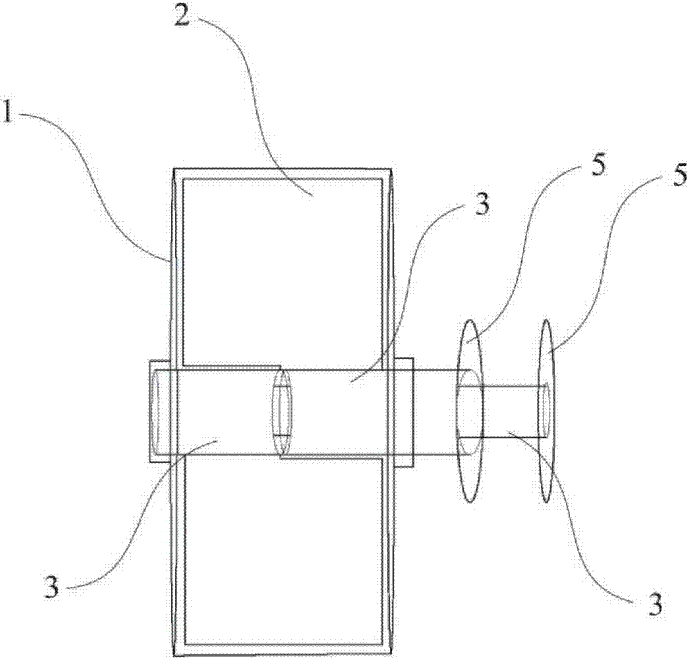
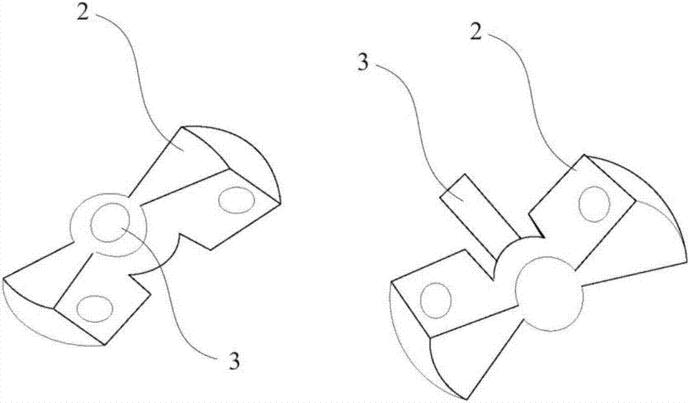
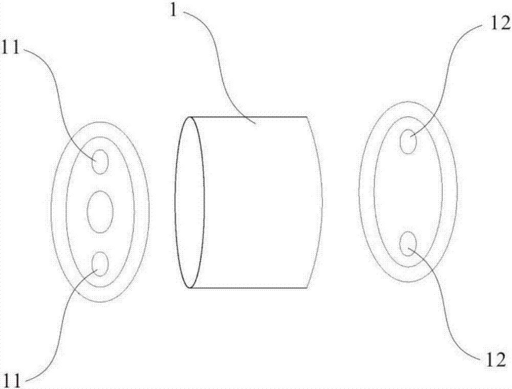
[0023] refer to figure 1 and Image 6 As shown, one embodiment of the present invention is a wheel-driven rotor compressor, including a compression cavity 1, the compression cavity 1 is cylindrical, and the end covers at both ends of the compression cavity 1 need to be respectively provided with air intake port 11 and air outlet 12, the structure of the compression cavity 1 is as follows image 3 shown; more importantly, two wheel blades 2 are installed inside the aforementioned compression cavity 1, and the structure of the two wheel blades 2 is as follows figure 2 As shown, and the positions of the two rotating blades 2 are staggered from each other, the two rotating blades 2 also need to cooperate with the internal structure of the compression chamber 1, specifically the radial outer edges of the two rotating blades 2 It is in close contact with the inner side ...


PUM


Abstract

The invention discloses a wheel moving type rotor compressor, and belongs to refrigerant compressors. A compression cavity is cylindrical, an air inlet and an air outlet are formed in end covers at the two ends of the compression cavity, two wheel moving blades are arranged in the compression cavity, and are staggered in position, the radial outer edge of the two wheel moving blades is in tight contact with the inner side of the compression cavity, and the axial outer edges of the two wheel moving blades are in tight contact with the end in the compression cavity; a transmission motor drives the two wheel moving blades to intermittently rotate in the compression cavity, the two wheel moving blades serve as a fixed piece which stays still and a movable piece rotatably compressing gas in turn, and repeated circulation is carried out, so that the compression aim is achieved; the two wheel moving blades carry out compression in turn, and therefore the compressor has the higher compression displacement, the compression ratio is high, the wheel moving blades in the compression cavity are driven by an external transmission motor, too high work temperature can be avoided, and the application field of an air energy heat pump can be effectively widened.

Description

technical field [0001] The invention relates to a refrigerant compressor, and more specifically, the invention mainly relates to a wheel-driven rotor compressor. Background technique [0002] At present, the maximum operating temperature of air energy heat pumps (including carbon dioxide heat pumps) must be controlled below 90 degrees Celsius. If the operating temperature is higher than 100 degrees Celsius, the internal motor will be burned. The above-mentioned reasons for burning the motor are mainly caused by mechatronics, that is, the compressor of the ordinary heat pump and the driving motor are sealed in a steel tank. When the motor is working, the temperature of the stator coil is already high. If the temperature increases, the internal resistance of the coil will When the internal resistance increases, the efficiency of the motor decreases. When the efficiency decreases, if the load remains unchanged, the coil current will continue to increase, entering the aforementi...

Claims


Application Information

Patent Timeline
Patent Type & Authority Applications(China)
IPC IPC(8): F04C23/02F04C29/00
CPCF04C23/02F04C29/00F04C2240/20
Inventor 李志敏
Owner 四川熙缘科技有限公司
Why Eureka
Try Eureka