Novel air seal device

A new type of air shutoff technology, applied in loading/unloading, conveyor, transportation and packaging, etc., can solve the problems of increasing air leakage rate, affecting the service life of the motor, increasing the rotating load of the impeller, etc., and achieving the effect of continuous discharge

Pending Publication Date: 2018-05-22
安陆市永丰粮油机械制造有限公司
View PDF0 Cites 2 Cited by
  • Summary
  • Abstract
  • Description
  • Claims
  • Application Information

AI Technical Summary

Problems solved by technology

[0003] Most of the existing air lockers use geared motors to drive the impeller to rotate through chains and gears. This method has the following defects: 1. During the operation of the air locker, ropes, ribbons, and packaging threads in the materials are easily entangled on the impeller. On the other hand, increased wear and tear will increase the rotational load of the impeller, resulting in difficulty in feeding, setting

Method used


Image

  • Novel air seal device
  • Novel air seal device
  • Novel air seal device

Examples


Embodiment Construction

[0031] The principles and features of the present invention will be described below in conjunction with the accompanying drawings and specific embodiments. The examples given are only used to explain the present invention and are not intended to limit the scope of the present invention.

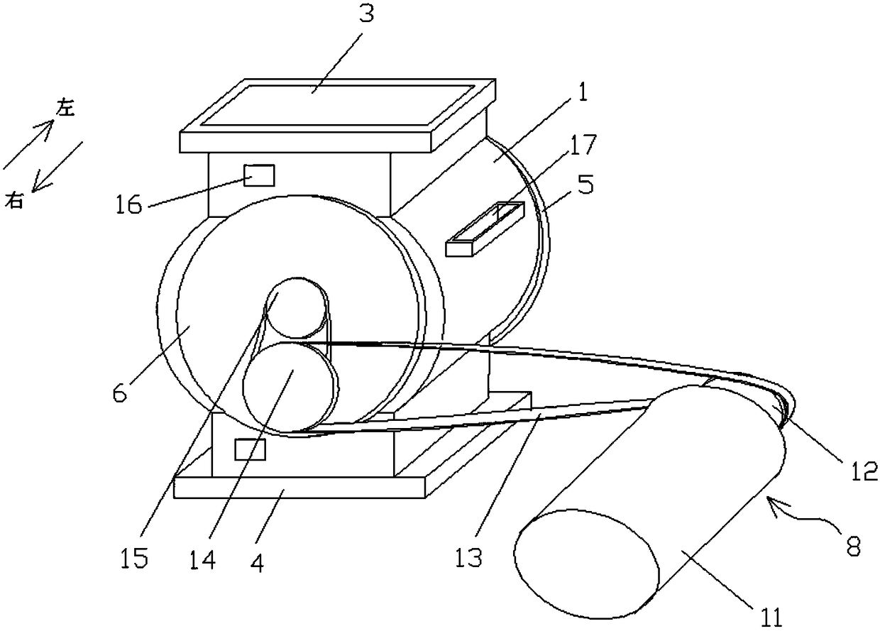
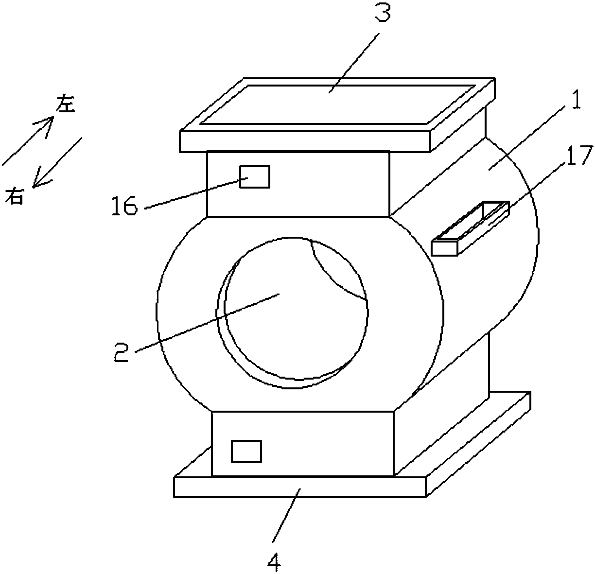
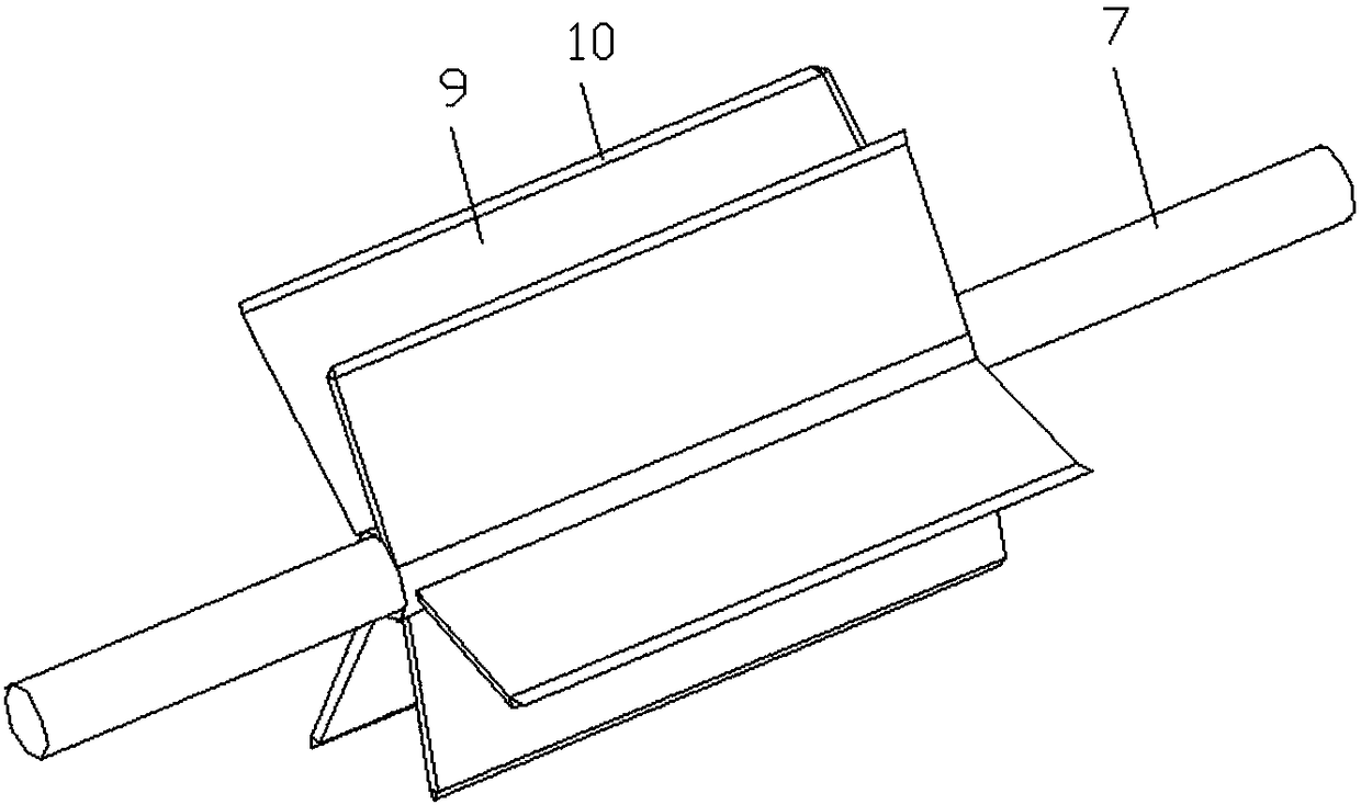
[0032] Such as figure 1 , figure 2 and image 3 As shown, the present invention provides a novel air lock, comprising a body 1, a cylindrical material cavity 2 is formed in the body 1, the upper end and the lower end of the body 1 are respectively provided with a feed port 3 and a discharge port 4, and the feed port 3 and the discharge port 4 can be welded on the upper and lower ends of the body 1, and the feed port 3 and the discharge port 4 can also be fixedly connected to the body 1 through flanges. Compared with welding, this connection method is more convenient for disassembly and assembly. At the same time, it is convenient for storage and saves space; the left and right sides of the...


PUM


Abstract

The invention relates to a novel air seal device comprising a device body. A cylindrical material cavity is formed in the device body; a feeding inlet and a discharging outlet are formed in the upperend and the lower end of the device body correspondingly; the left portion and the right portion of the device body are each provided with an opening communicating with the material cavity; a left endcover and a right end cover are arranged at the two openings correspondingly; an impeller shaft is horizontally arranged in the material cavity; one end of the impeller shaft is rotatably connected into a mounting groove formed in the inner side wall of the left end cover, and the other end of the impeller shaft penetrates through a through hole in the right end cover and then is in transmissionconnection with a belt gap bridge transmission device; the belt gap bridge transmission device is electrically connected with a control device; and an impeller is arranged on the impeller shaft, and the side, close to the inner wall of the material cavity, of the impeller is provided with a scraping device. The novel air seal device has the beneficial effects that the structure is simple, the device body and the end covers are arranged in a split mode, and thus disassembly, assembly and cleaning are very convenient; and meanwhile, a motor and the impeller shaft are in transmission connection through a belt, after a discharging channel is clamped, the motor can still rotate, the situation of burnout of the motor is avoided, the service life of the motor is prolonged, and the cost is saved.

Description

technical field [0001] The invention relates to the technical field of light blowers, in particular to a novel air shutoff device. Background technique [0002] The air shutoff device is widely used in the pneumatic transportation of equipment in rice milling, flour milling, feed, machinery and chemical industry, medicine, tobacco, metallurgy, cement and dust removal and the discharge of pipe network pressure state. For positive pressure and negative pressure state The powdery, granular, flake and fibrous materials below play the role of continuous discharge and air tightness. The air shutoff device is an important device in the pneumatic conveying and ventilation and dust removal network. The air shutoff device is installed at the discharge port of the unloader or cyclone dust collector. Its main function has two aspects: one is to ensure the smooth discharge of materials, and it is closed Working air flow, its structural composition includes the impeller casing and the im...

Claims


Application Information

Patent Timeline
IPC IPC(8): B65G65/48B65G53/46
CPCB65G53/46B65G65/48
Inventor 胡宝华
Owner 安陆市永丰粮油机械制造有限公司
Why Eureka
Try Eureka