Sparse target spectrum real-time detection system

A real-time detection and target technology, applied in the field of spectral imaging, can solve the problems of high resolution and low error, and achieve the effect of increasing the amount of observation, large field of view, and high energy utilization rate

Active Publication Date: 2017-09-19
ACAD OF OPTO ELECTRONICS CHINESE ACAD OF SCI
View PDF6 Cites 1 Cited by
  • Summary
  • Abstract
  • Description
  • Claims
  • Application Information

AI Technical Summary

Problems solved by technology

[0006] The object of the present invention is to provide a real-time detection system of sparse target spectrum, which can solve the problem of real-time detection of sparse target spectrum, and has higher resolution and lower error

Method used


Image

  • Sparse target spectrum real-time detection system

Examples


Embodiment Construction

[0015] The technical solutions in the embodiments of the present invention will be clearly and completely described below in conjunction with the accompanying drawings in the embodiments of the present invention. Obviously, the described embodiments are only some of the embodiments of the present invention, not all of them. Based on the embodiments of the present invention, all other embodiments obtained by persons of ordinary skill in the art without making creative efforts belong to the protection scope of the present invention.

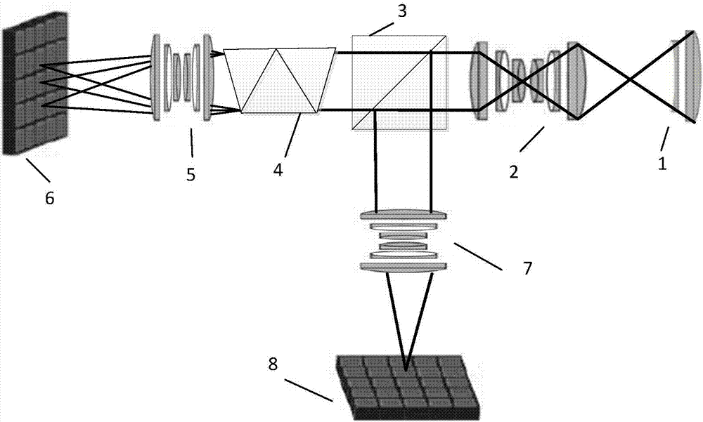
[0016] figure 1 It is a schematic structural diagram of a real-time detection system for a sparse target spectrum provided by an embodiment of the present invention. Such as figure 1 As shown, it mainly includes: a front mirror 1, a collimating mirror 2, a dichroic prism 3, a dispersion element 4, a first imaging mirror 5, a first detector 6, a second imaging mirror 7, and a second detector 8;

[0017] Among them, the front mirror 1 images an obj...


PUM


Abstract

The present invention discloses a sparse target spectrum real-time detection system. The system comprises a pre-mirror, a collimating mirror, a beam splitter prism, a dispersion element, a first imaging mirror, a first detector, a second imaging mirror and a second detector; the pre-mirror images an infinitely far target on the front focal plane of the collimating mirror; light is collimated into parallel light by the collimating mirror; the parallel light is split into two light beams of the same energy through the beam splitter prism; one of the two light beams passes through the dispersion element, and then, dispersed light is imaged on the first detector through the first imaging mirror, and therefore, the target is dispersed into images of different wavelengths, and the images are imaged at different positions; and the other light beam passes through the second imaging mirror and is imaged on the second detector, and the position distribution of the sparse target is recorded. With the system adopted, the problem of the spectrum real-time detection of the sparse target can be solved. The system has high resolution and low error.

Description

technical field [0001] The invention relates to the technical field of spectral imaging, in particular to a real-time detection system for sparse target spectrum. Background technique [0002] Man-made celestial bodies play an important role in the operation of society, but because these objects are difficult to recycle and become space garbage after being discarded, in some cases, they pose a threat to other normal operating man-made celestial bodies, so it is necessary to detect space objects in real time and identification. [0003] The basic purpose of space target detection is to convert various electromagnetic waves independently generated and passively reflected by space targets into detectable forms to complete the monitoring and identification of space targets. At present, there are mainly long-range warning radars, astronomical telescopes, radio signal monitoring, precision tracking radars, phase control radars, artificial satellite optical cameras, and photoelect...

Claims


Application Information

Patent Timeline
Patent Type & Authority Applications(China)
IPC IPC(8): G01J3/28
Inventor 王建威吕群波李伟艳张丹丹裴琳林刘扬阳赵娜
Owner ACAD OF OPTO ELECTRONICS CHINESE ACAD OF SCI
Why Eureka
Try Eureka