Eureka AIR delivers breakthrough ideas for toughest innovation challenges, trusted by R&D personnel around the world.

Rare earth metal carbon content rapid detection device

A rare-earth metal and detection device technology, applied in measuring devices, material weighing, instruments, etc., can solve the problems of high labor intensity, high price, long detection cycle, etc., achieve high reliability, low cost, and shorten the quality inspection cycle Effect

Active Publication Date: 2020-04-03
JIANGXI IONIC RARE EARTH ENG RES CO LTD
View PDF10 Cites 0 Cited by
  • Summary
  • Abstract
  • Description
  • Claims
  • Application Information

AI Technical Summary

Problems solved by technology

The disadvantages of the above technology are: first, the carbon-sulfur analyzer is a precision instrument, the price is high, it needs to be operated by professionals, and depends on the operating level of the operator; second, the detection period is long, and the detection process needs to go through drilling, sampling, Testing and other processes cannot be detected online in real time; third, the detection results of the carbon-sulfur analyzer are accurate, but in actual production, it is only necessary to know the range of carbon content in rare earth metals, such as 200-300ppm or 300-400ppm, and Its exact value is not required, such as 265ppm; Fourth, each piece of metal needs to be sampled by manual drilling, which is labor-intensive
[0004] Some quality inspectors will roughly judge whether the metal is qualified by the hardness of the bench drill drilled on the metal. This method has very poor reliability and cannot meet the requirements of on-site inspection.

Method used


Image

  • Rare earth metal carbon content rapid detection device

Examples


Embodiment Construction

[0016] The following describes the technical solutions in the embodiments of the present invention clearly and completely with reference to the specific content of the present invention. Obviously, the described embodiments are only a part of the embodiments of the present invention, rather than all the embodiments. Based on the embodiments of the present invention, all other embodiments obtained by those of ordinary skill in the art without creative work shall fall within the protection scope of the present invention.

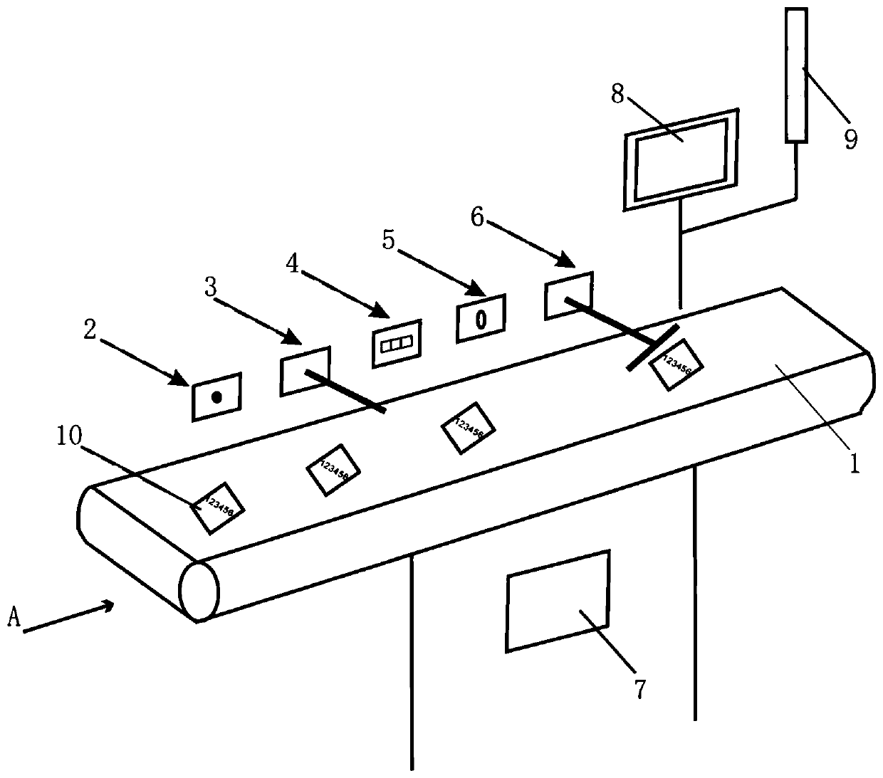
[0017] Such as figure 1 As shown, an embodiment of the present invention provides a rapid detection device for the carbon content of rare earth metals, including:

[0018] Belt conveyor and dynamic weighing device 1, with brackets and pulleys at the bottom;

[0019] A metal position detection device 2, a vibration exciter 3, a microphone 4, a camera 5 and a sorting device 6 are sequentially arranged above the belt conveying and dynamic weighing device 1 from the fro...


PUM


Abstract

The invention discloses a rapid detection device for the carbon content of rare earth metals. The rapid detection device comprises a belt conveying and dynamic weighing device, a computer, a display screen and an indication beacon, wherein a bracket is arranged at the bottom of the belt conveying and dynamic weighing device; a metal position detection device, a vibration exciter, a microphone, a camera and a sorting device are sequentially arranged above the belt conveying and dynamic weighing device from front to back at intervals; the computer is respectively in communication connection with each part and can be used for receiving signals of each part to cooperatively control each part as well as analyzing a sound signal of the microphone to obtain the carbon content of rare earth metals detected by the belt conveying and dynamic weighing device; the display screen is arranged above the belt conveying and dynamic weighing device, is located behind the sorting device and is in communication connection with the computer; and the indication beacon is arranged behind the display screen, is located above the rear end of the belt conveying and dynamic weighing device and is in communication connection with the computer. The rapid detection device can be used for continuously and rapidly detecting the carbon content of the metals and sorting the metals online without artificial participation, and is high in detection efficiency, simple in integral structure and convenient to operate.

Description

Technical field [0001] The invention relates to the field of metal detection, in particular to a rapid detection device for the carbon content of rare earth metals. Background technique [0002] Mixed rare earth metals and single rare earth metals at home and abroad are often produced by molten salt electrolysis. When preparing rare earth metals by molten salt electrolysis, the carbon element in the graphite anode and the electrolytic cell will inevitably enter the metal. Excessive carbon content will affect the rare earth metal. The quality of the impact. [0003] At present, the detection of carbon content in rare earth metals first requires manual drilling and sampling of different parts of the metal, and after obtaining metal samples, a carbon-sulfur analyzer is used to detect the carbon content in rare earth metals. Its working principle is: after the oxygen as the carrier gas is purified, it is introduced into the resistance furnace or high-frequency furnace as the combustio...

Claims


Application Information

Patent Timeline
Patent Type & Authority Patents(China)
IPC IPC(8): G01N5/00G01N29/04
CPCG01N5/00G01N29/045G01N2291/0234
Inventor 李建中伍昕宇杨新华管新地李华杰杨威黄德晟潭水淋
Owner JIANGXI IONIC RARE EARTH ENG RES CO LTD
Why Eureka
Eureka Blog
Learn More