A method for locating transmission line faults

A transmission line, fault location technology, applied in the direction of fault location, fault detection according to conductor type, information technology support system, etc., to achieve the effect of high engineering practical significance and easy realization.

Active Publication Date: 2019-07-16
CHINA UNIV OF MINING & TECH
View PDF7 Cites 0 Cited by
  • Summary
  • Abstract
  • Description
  • Claims
  • Application Information

AI Technical Summary

Problems solved by technology

[0005] In order to solve the technical problems raised by the above-mentioned background technology, the present invention aims to provide a transmission line fault location method, which overcomes the problems existing in the traditional traveling wave method, and uses the linear lag principle of the phase when the modulus voltage traveling wave propagates to perform fault location, which is simple Easy to implement

Method used


Image

  • A method for locating transmission line faults
  • A method for locating transmission line faults
  • A method for locating transmission line faults

Examples


Embodiment Construction

[0038] The technical solutions of the present invention will be described in detail below in conjunction with the accompanying drawings.

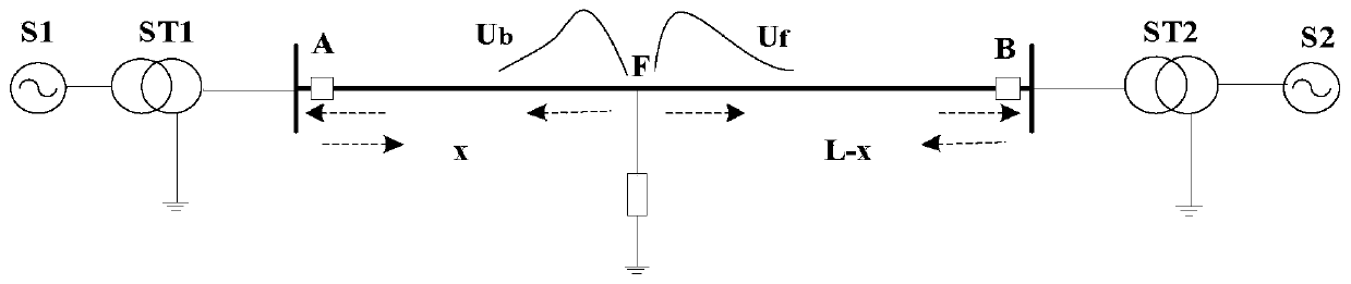
[0039] The schematic diagram of the double-ended transmission line is as follows: figure 1 As shown, where A and B are the measurement points at both ends of the transmission line, F is the fault point, x is the distance from the fault point to point A, L is the total length of the line, Ub and Uf are the initial traveling waves of the reverse and forward voltages, respectively. S1 and S2 are double-ended power supplies respectively, and ST1 and ST2 are corresponding power transformers respectively. The dotted arrow in the figure indicates the direction of initial traveling wave propagation.

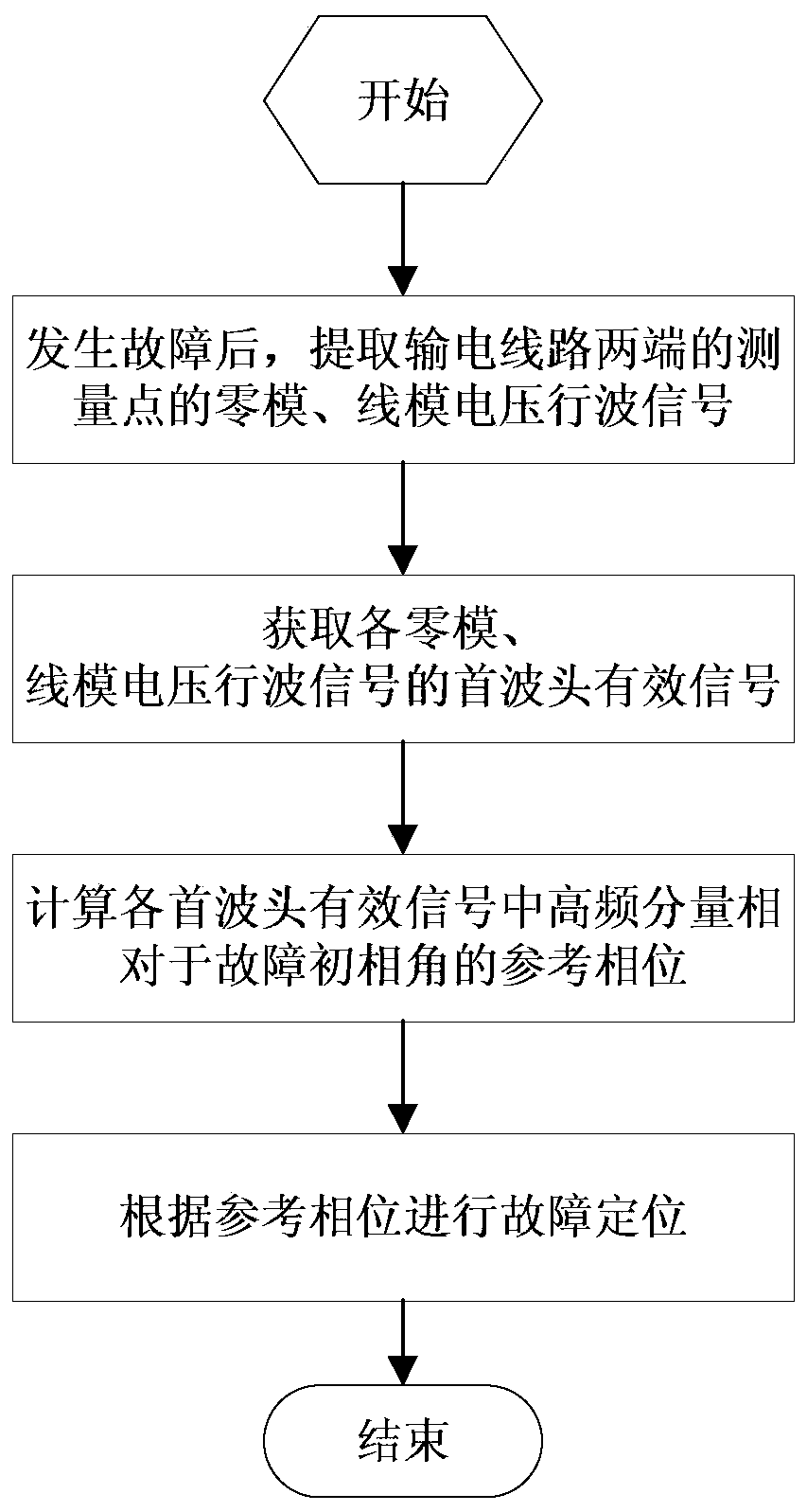
[0040] A transmission line fault location method, such as figure 2 As shown, the specific steps are as follows.

[0041] Step 1: After the fault occurs, extract the original voltage traveling wave signals of points A and B respectively, and then p...


PUM


Abstract

The invention discloses a power transmission line fault locating method. The power transmission line fault locating method includes the steps: extracting the zero mode and line mode voltage traveling wave signals at a measuring point; acquiring the head wave front effective signal of each zero mode voltage traveling wave signal and each line mode voltage traveling wave signal; calculating the reference phase, of a high frequency component, relative to a fault initial phase angle, in each head wave front effective signal; and finally performing fault locating according to the reference phase. The power transmission line fault locating method overcomes the problem existing in a traditional traveling wave method, performs fault locating by utilizing the linear lagging principle of the phase during the modulus voltage traveling wave propagating process, and is simple to implement.

Description

technical field [0001] The invention belongs to the technical field of grid fault location, and in particular relates to a transmission line fault location method. Background technique [0002] With the vigorous advancement of AC transmission construction in my country, automatic and accurate fault location technology is becoming more and more important. The area affected by the fault of the transmission line is wider than that of the distribution line, and the distance of the transmission line is long, and the line parameters have obvious frequency-dependent characteristics, which makes it difficult to locate the fault. Therefore, accurate, reliable, and practical fault location methods play an important role in quickly troubleshooting, reducing losses of all parties, and maintaining system stability. [0003] At present, transmission line fault location can be divided into: impedance method, traveling wave method and intelligent method. The impedance method uses the rela...

Claims


Application Information

Patent Timeline
Patent Type & Authority Patents(China)
IPC IPC(8): G01R31/08
CPCG01R31/086Y04S10/52
Inventor 梁睿彭楠刘成磊宋超然杨智
Owner CHINA UNIV OF MINING & TECH
Why Eureka
Try Eureka