Ultraviolet sterilization apparatus
A sterilizing device and ultraviolet technology, which is applied in water supply devices, disinfection, construction, etc., can solve the problems of dead angles, time-consuming and labor-intensive problems, and achieve the effect of complete sterilization and disinfection
- Summary
- Abstract
- Description
- Claims
- Application Information
AI Technical Summary
Problems solved by technology
Method used
Image

Examples
Embodiment 1
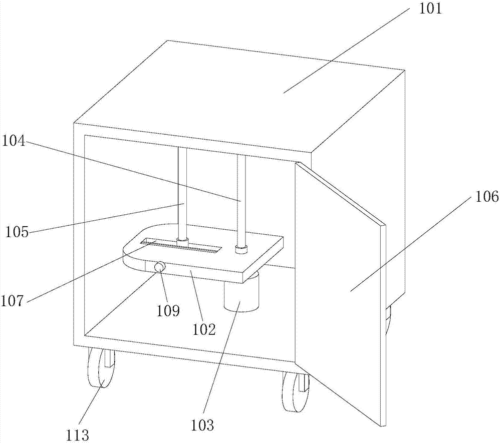
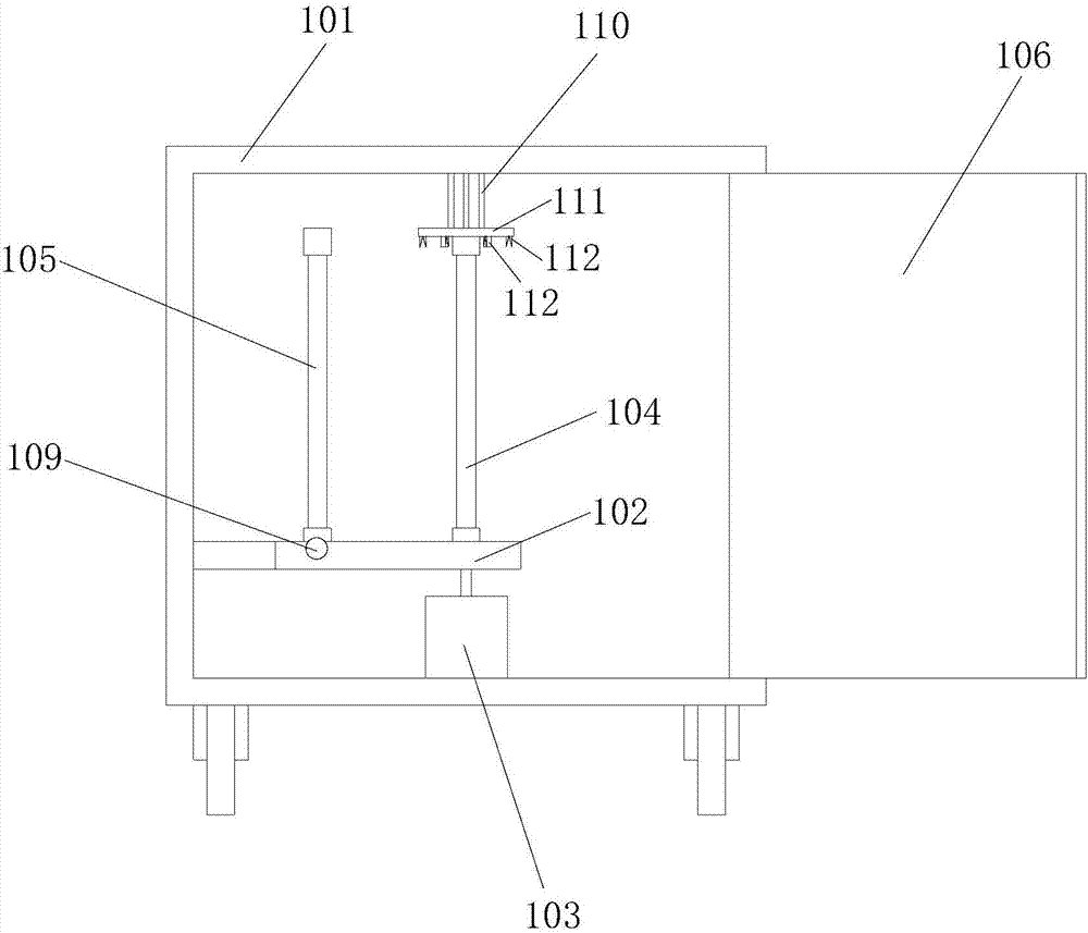
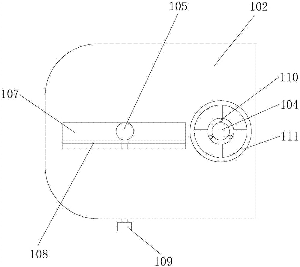
[0030] figure 1 Schematic diagram of the structure of the ultraviolet sterilizing device provided by Embodiment 1 of the present invention; figure 2 for figure 1 main view of image 3 It is a top view of the internal structure of the ultraviolet sterilizing device provided in Embodiment 1 of the present invention (cabinet 101 is not shown). see Figure 1 to Figure 3 As shown, the present embodiment provides an ultraviolet sterilizing device, including a box body 101 and a bracket; the inside of the box body 101 is provided with a base 102 and a drive mechanism 103, preferably, the base 102 is flat, and the base 102 is provided with a second An ultraviolet lamp 104 and the second ultraviolet lamp 105, as preferably, the first ultraviolet lamp 104 is fixedly connected with the base 102, the power output shaft of the driving mechanism 103 is connected with the transmission of the base 102, and the axis of the power output shaft of the driving mechanism 103 is connected with t...
Embodiment 2
[0055] Figure 4 Schematic diagram of the structure of the ultraviolet sterilizing device provided by Embodiment 2 of the present invention; Figure 5 for Figure 4 main view of Figure 6 It is a schematic diagram of the internal structure of the ultraviolet sterilizing device provided in Embodiment 2 of the present invention (cabinet 101 is not shown). see Figure 4 to Figure 6 As shown, this embodiment also provides a kind of ultraviolet sterilizing device, and the ultraviolet sterilizing device of this embodiment has described another kind of realization scheme that support and first ultraviolet lamp 104 and second ultraviolet lamp 105 are relatively rotated, besides The technical solution of Embodiment 1 also belongs to this embodiment, and will not be described again here. The same components use the same reference numerals as in the first embodiment, and reference is made to the description of the first embodiment.
[0056] The ultraviolet sterilizing device provide...
PUM
 Abstract
Description
Claims
Application Information