Elevator braking device and lifting mechanism thereof

A technology of lifting mechanism and elevator speed limiter, which is applied in the field of elevators, can solve the problems of potential safety hazards and difficulty in ensuring safe braking of the car, and achieve the effects of improving safety, simple structure, and preventing loosening

Active Publication Date: 2017-09-22
IFE ELEVATORS
View PDF17 Cites 1 Cited by
  • Summary
  • Abstract
  • Description
  • Claims
  • Application Information

AI Technical Summary

Problems solved by technology

It is difficult to ensure the safe braking of the car, and there are potential safety hazards

Method used


Image

  • Elevator braking device and lifting mechanism thereof
  • Elevator braking device and lifting mechanism thereof
  • Elevator braking device and lifting mechanism thereof

Examples


Embodiment Construction

[0025] Embodiments of the present invention will now be described with reference to the drawings, in which like reference numerals represent like elements.

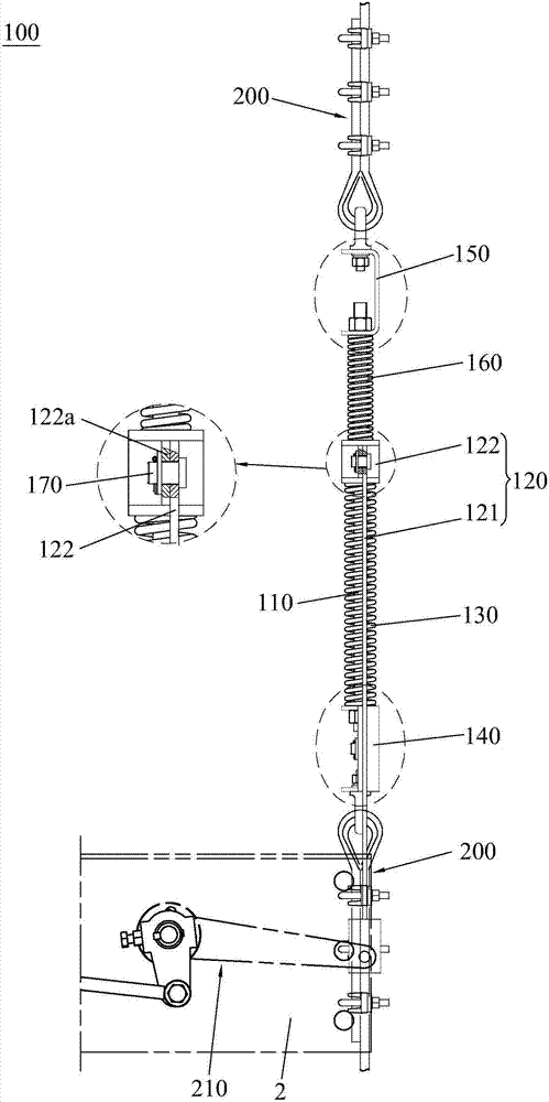
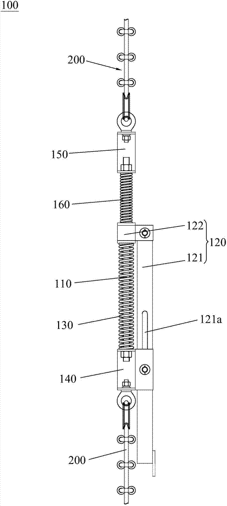
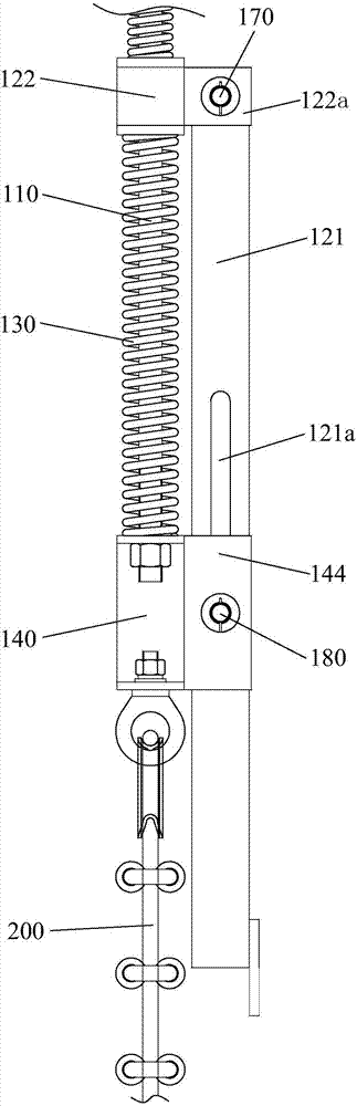
[0026] combine first Figure 1-2 , 6, the pulling mechanism 100 provided by the present invention is suitable for the speed governor 10 with automatic reset function, so that the steel wire rope 200 connected to the speed governor 10 is connected to the elevator car through the pulling mechanism 100. Safety gear device 210 on the car.

[0027] Concrete combination figure 1 , 6 As shown, the upper end of the wire rope 200 bypasses the overspeed governor 10, the lower end of the wire rope 200 bypasses the tensioning device 20, and the two ends of the wire rope 200 are connected by the pulling mechanism 100. Therefore, the wire rope 200 and the pulling mechanism 100 form a A ring-shaped wrapping unit 30, and the lifting mechanism 100 is also connected to the safety gear device 210 on the elevator car 2. The setting of the...


PUM


Abstract

The invention discloses a lifting mechanism which comprises a guide shaft rod, a sliding part and a first elastic part. The two ends of the guide shaft rod are connected to the position between a speed limiter and a tensioning device through steel wire ropes. One end of the sliding part is in sliding connection with the guide shaft rod, and the other end of the sliding part is connected to a security clamp device. The two ends of the first elastic part abut against the sliding part and the guide shaft rod in a contact mode correspondingly. When a car drives the sliding part to slide, the first elastic part is deformed. Due to the fact that the lifting mechanism is added between the speed limiter and the tensioning device, when the speed limiter stalls, the car continues to move downwards to pull the sliding part to move downwards, and then the first elastic part is compressed to produce lifting force so as to enable the security clamp to act. When a counter weight is thrown up and drops down, the counter weight drives the car to move upwards, the whole formed by the steel wire ropes and the lifting mechanism is kept still due to the existence of the first elastic part, accordingly, the speed limiter is prevented from being automatically reset, the car is prevented from being repeatedly braked, and security is improved. The invention further discloses an elevator braking device with the lifting mechanism.

Description

technical field [0001] The invention relates to the technical field of elevators, in particular to a pulling mechanism suitable for an elevator speed governor with an automatic reset function and an elevator braking device with the lifting mechanism. Background technique [0002] Elevators are mainly composed of guide rails, traction machines, counterweights, cars, safety devices (such as speed limiters, safety gears and buffers, etc.), signal control systems, and hall doors. In the machine room, wire rope friction transmission is usually used. After the wire rope goes around the traction sheave, its two ends are respectively connected to the car and the counterweight. The motor drives the traction sheave to rotate to drive the car up and down. [0003] Elevators need to meet the requirements of safety and reliability, high conveying efficiency, accurate leveling, and comfortable rides when they are in use. However, in real life, various elevator accidents often occur, such ...

Claims


Application Information

Patent Timeline
Patent Type & Authority Applications(China)
IPC IPC(8): B66B5/04B66B5/14
CPCB66B5/04B66B5/14
Inventor 赵兴准雷树礼
Owner IFE ELEVATORS
Why Eureka
Try Eureka