Application of carbon tube film in anisotropic polymer preparing

An anisotropic, carbon tube film technology, which is applied in the field of preparation of polymer/carbon tube composite film materials, can solve problems such as waste of resources, and achieve the effects of low filler dosage and simple preparation method.

Active Publication Date: 2017-09-22
TIANJIN UNIV
View PDF4 Cites 0 Cited by
  • Summary
  • Abstract
  • Description
  • Claims
  • Application Information

AI Technical Summary

Problems solved by technology

However, the anisotropic materials currently prepared are anisotropic in the plane and vertical directions, and only when a large amount of filler is added can they show anisotropy, which wastes resources.

Method used


Image

  • Application of carbon tube film in anisotropic polymer preparing
  • Application of carbon tube film in anisotropic polymer preparing
  • Application of carbon tube film in anisotropic polymer preparing

Examples


Embodiment 1

[0023] (1) Carbon tube membrane modification: Add 0.01 mol / L p-phenylenediamine solution dropwise to 0.1 mol / L HCl solution at a volume ratio of 1:1 to obtain an acidic p-phenylenediamine solution. At 0°C, add 0.01 mol / L sodium nitrite solution dropwise to the acidic p-phenylenediamine solution at a molar mass ratio of 1:1 for reaction to obtain a dark red diazonium salt solution. At room temperature, the carbon tube membrane was placed in a diazonium salt solution and reacted for 12 hours. The sample was taken out and washed repeatedly with deionized water, ethanol and acetone to obtain a modified carbon tube membrane.

[0024] (2) Using the modified carbon tube film as the substrate, compounding the polyurethane and the carbon tube film, annealing at a stepwise temperature rise within the range of 50-400° C., to obtain a polyurethane / carbon tube composite thin film material.

Embodiment 2

[0026](1) Carbon tube membrane modification: Add 0.5 mol / L p-phenylenediamine solution dropwise to 0.1 mol / L HCl solution at a volume ratio of 1:1 to obtain an acidic p-phenylenediamine solution. At 0°C, add 0.5 mol / L sodium nitrite solution dropwise to the acidic p-phenylenediamine solution at a molar mass ratio of 1:1 for reaction to obtain a dark red diazonium salt solution. At room temperature, the carbon tube membrane was placed in a diazonium salt solution and reacted for 20 h. The sample was taken out and washed repeatedly with deionized water, ethanol and acetone to obtain a modified carbon tube membrane.

[0027] (2) Using the modified carbon tube film as the substrate, compounding the polyimide acid and the carbon tube film, and annealing in the range of 50-400° C. to obtain the polyimide / carbon tube composite thin film material.

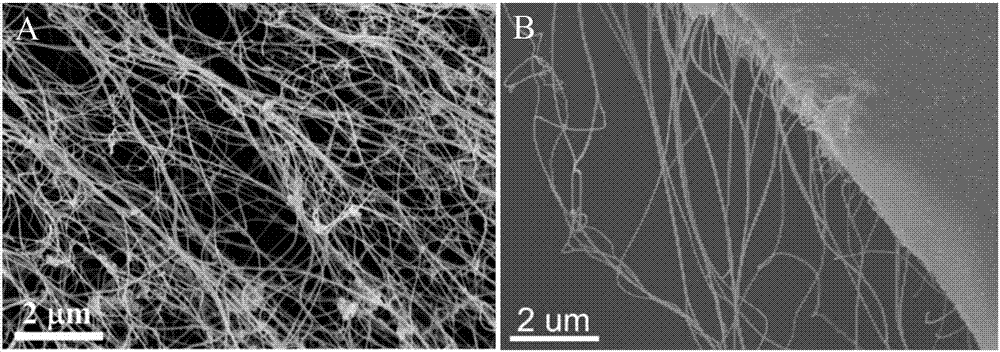
[0028] figure 1 SEM images of carbon tube film and polyimide / carbon tube composite film. from figure 1 (A) It can be seen that the ca...

Embodiment 3

[0032] (1) Carbon tube membrane modification: Add 0.01 mol / L p-phenylenediamine solution dropwise to 0.1 mol / L HCl solution at a volume ratio of 1:1 to obtain an acidic p-phenylenediamine solution. At 0°C, add 0.01 mol / L sodium nitrite solution dropwise to the acidic p-phenylenediamine solution at a molar mass ratio of 1:1 for reaction to obtain a dark red diazonium salt solution. At room temperature, the carbon tube membrane was placed in a diazonium salt solution and reacted for 12 hours. The sample was taken out and washed repeatedly with deionized water, ethanol and acetone to obtain a modified carbon tube membrane.

[0033] (2) Using the modified carbon tube film as a substrate, compounding polystyrene and carbon tube film, and annealing at a stepwise temperature rise within the range of 50-400° C., to obtain a polystyrene / carbon tube composite thin film material.


PUM

PropertyMeasurementUnit
tensile strengthaaaaaaaaaa
electrical resistanceaaaaaaaaaa

Abstract

The invention discloses application of a carbon tube film in anisotropic polymer preparing. A modified carbon tube film is coated with polyimide acid in a spinning mode to perform carbon tube film composition, and annealing is conducted in a range of 50-400 DEG C. The application of the carbon tube film in the anisotropic polymer preparing is simple in method, short in period, fast and efficient, easy to operate and low in cost. Oriented carbon tube films are added, and thus mechanical properties of a composite film material are drastically improved, and the composite film material has obvious anisotropy in the horizontal and vertical directions in a plane.

Description

[0001] The application of the present invention is a divisional application of the parent application "Preparation method of anisotropic polymer / carbon tube composite film material". The application number of the parent application is 201510195613X, and the application date is April 23, 2015. technical field [0002] The invention relates to a preparation method of an anisotropic polymer / carbon tube composite thin film material, which has important application prospects in the fields of aerospace, electronic information, automobile industry and the like. The invention belongs to the field of preparation of composite materials. Background technique [0003] In recent years, polymer composite materials have been widely used in energy, information, electronics, molecular devices, etc., and polymer composite materials with anisotropy provide a greater potential space for the application of composite materials. The orientation of the material can fully exert the potential of the ...

Claims


Application Information

Patent Timeline
Patent Type & Authority Applications(China)
IPC IPC(8): C08L75/04C08L79/08C08L25/06C08L27/18C08K9/04C08K7/24C08J5/18
CPCC08J5/18C08J2325/06C08J2327/18C08J2375/04C08J2379/08C08K7/24C08K9/04C08L2203/16C08L79/08C08L25/06C08L27/18C08L75/04
Inventor 封伟李双雯冯奕钰
Owner TIANJIN UNIV
Why Eureka
Try Eureka