Dedicated tool car for 35kV transformer replacement

A special tool and transformer technology, applied in switchgear, electrical components and other directions, can solve the problems of inconvenient disassembly and installation of transformers, long power outage time for replacement of transformers, and long time for replacement of transformers, and reduce working time. and labor intensity, reduce the scope of power outages, and facilitate the reliability of power supply.

Inactive Publication Date: 2017-09-22
STATE GRID HEILONGJIANG ELECTRIC POWER CO LTD ELECTRIC POWER RES INST +1
View PDF4 Cites 1 Cited by
  • Summary
  • Abstract
  • Description
  • Claims
  • Application Information

AI Technical Summary

Problems solved by technology

[0004] The purpose of the present invention is to solve the problem that the construction distance between substation equipment in some early construction substations is small, the replacement of transformers has a long power outage time, and the power outage range is large, which brings inconvenience to the reliability of power supply; and It takes a long time for the staff to replace the transformer, and it is inconvenient to disassemble and install the transformer, which causes a large workload for the staff

Method used


Image

  • Dedicated tool car for 35kV transformer replacement
  • Dedicated tool car for 35kV transformer replacement
  • Dedicated tool car for 35kV transformer replacement

Examples


specific Embodiment approach 1

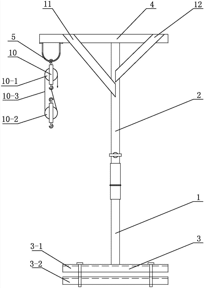
[0020] Specific implementation mode one: combine figure 1 and figure 2 Describe this embodiment, a kind of 35kV mutual inductor of this embodiment replaces special-purpose tool cart, it comprises upper bracket 1, lower bracket 2, base 3, support pipe 4, hook 5, left operating handle 6, right operating handle 7 and The pulley block 10, the upper bracket 1 and the lower bracket 2 are hollow cylindrical brackets, the base 3 is arranged horizontally, one end of the upper bracket 1 is vertically fixed to the middle of the upper end of the base 3, and one end of the lower bracket 2 rotates with the other end of the upper bracket 1 Fixed connection, the other end of the lower bracket 2 is fixed to the support tube 4, the hook 5 is installed on one end of the support tube 4, one end of the pulley block 10 is fixed to the hook 5, the other end of the pulley block 10 is connected to the transformer, and the left operating handle 6 and one end of the right operating handle 7 are respec...

specific Embodiment approach 2

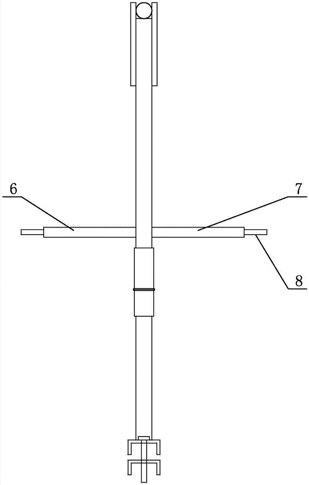
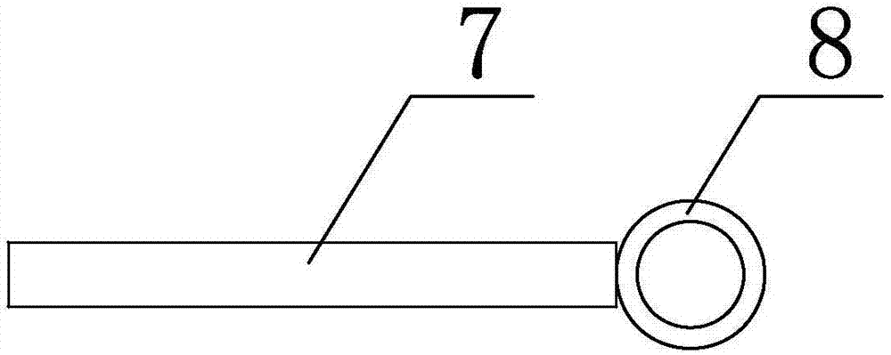
[0022] Specific implementation mode two: combination figure 2 and image 3 Describe this embodiment, this embodiment also includes two connecting rings 8, and the two connecting rings 8 are fixedly connected to the other ends of the left operating handle 6 and the right operating handle 7 respectively. In this way, since the left operating handle 6 and the right operating handle 7 are relatively high from the ground, it is difficult for the staff to operate them while standing on the ground. The other ends of the left operating handle 6 and the right operating handle 7 are fixedly connected with two connecting rings 8 The staff can rotate the left operating handle 6 and the right operating handle 7 by 360° through the rope. Other compositions and connections are the same as in the first embodiment.

specific Embodiment approach 3

[0023] Specific implementation mode three: combination figure 1 Describe this embodiment, this embodiment also includes a first reinforcement board 11 and a second reinforcement board 12, one end of the first reinforcement board 11 is fixedly connected with the upper bracket 1, and the other end of the first reinforcement board 11 is connected with one end of the support tube 4 For fixed connection, one end of the second reinforcement plate 12 is fixedly connected with the upper bracket 1 , and the other end of the second reinforcement plate 12 is fixedly connected with the other end of the support tube 4 . In this way, the first reinforcement plate 11 and the second reinforcement plate 12 can increase the connection strength between the upper bracket 1 and the support tube 4, effectively improving the stability and safety of the upper bracket 1 and the support tube 4 during operation. Other compositions and connections are the same as those in Embodiment 1 or Embodiment 2.


PUM


Abstract

The utility model relates to a special tool cart for replacing a 35kV transformer, which relates to the field of power tools. In order to solve the problem that the construction distance between substation equipment in some existing early construction substations is small, the replacement of transformers has a long power outage time and a large power outage range, which brings inconvenience to the reliability of power supply; and the staff replace The transformer takes a long time, and it is inconvenient to disassemble and install the transformer, which causes a large workload for the staff. The base of the present invention is arranged horizontally, one end of the upper bracket is fixed vertically on the middle of the upper end of the base, one end of the lower bracket is fixedly connected to the other end of the upper bracket by rotation, the other end of the lower bracket is fixedly connected to the support tube, and the hook is installed on the support tube One end of the pulley block is fixedly connected to the hook, the other end of the pulley block is connected to the transformer, one end of the left operating handle and the right operating handle are respectively fixed on both sides of the middle of the upper bracket, and the base is fixed on the channel steel frame of the transformer . The invention is used to replace the 35kV transformer.

Description

technical field [0001] The invention relates to the field of power tools, in particular to a special tool cart for replacing 35kV transformers. Background technique [0002] At present, the work of replacing current transformers and voltage transformers in power systems is very common, and the work of replacing transformers is very cumbersome. The construction distance between substation equipment in some early-built substations is small, and the distance between adjacent transformers is only 1.5 meters. The interval between the interval and the adjacent interval is only 2m to 3m. The replacement of the transformer requires a long-term power outage, and the power outage range is large. Reliability brings inconvenience. [0003] To sum up, the construction distance between substation equipment in some early-stage construction substations is small, and the replacement of transformers has a long power outage time and a large power outage range, which brings inconvenience to th...

Claims


Application Information

Patent Timeline
Patent Type & Authority Applications(China)
IPC IPC(8): H02B3/00
CPCH02B3/00
Inventor 周洪毅田玉恒张洪达张健孙巍孙海明郭跃男
Owner STATE GRID HEILONGJIANG ELECTRIC POWER CO LTD ELECTRIC POWER RES INST
Why Eureka
Try Eureka