Aluminum material punching mechanism

An aluminum material and perforated plate technology, which is applied to the processing of aluminum profiles and the field of aluminum material punching mechanism, can solve the problems of difficulty in production and use, deformation of aluminum materials, complex structure, etc., to achieve efficient and accurate drilling processing, and avoid distortion. Deformation, reasonable structural design effect

Inactive Publication Date: 2017-09-26
张雅婷
View PDF6 Cites 5 Cited by
  • Summary
  • Abstract
  • Description
  • Claims
  • Application Information

AI Technical Summary

Problems solved by technology

In order to facilitate fixed installation, during the production process of aluminum, it is necessary to punch holes in the aluminum according to the needs of the installation. The existing aluminum punching device has a complicated structure and troublesome operation, and it is difficult to punch the aluminum quickly and efficiently. In the process of punching aluminum, because the punching round rod has a greater pressure on the aluminum during the punching process, and the aluminum is soft, especially the long aluminum, often punching holes in the aluminum The aluminum material is deformed during the process, and it is difficult to accurately punch the aluminum material according to the needs, reducing the production and processing quality of the aluminum material, and it is difficult to meet the needs of production and use.

Method used


Image

  • Aluminum material punching mechanism
  • Aluminum material punching mechanism

Examples


Embodiment Construction

[0011] In order to further describe the present invention, the specific implementation of an aluminum material punching mechanism will be further described below in conjunction with the accompanying drawings. The following examples are explanations of the present invention and the present invention is not limited to the following examples.

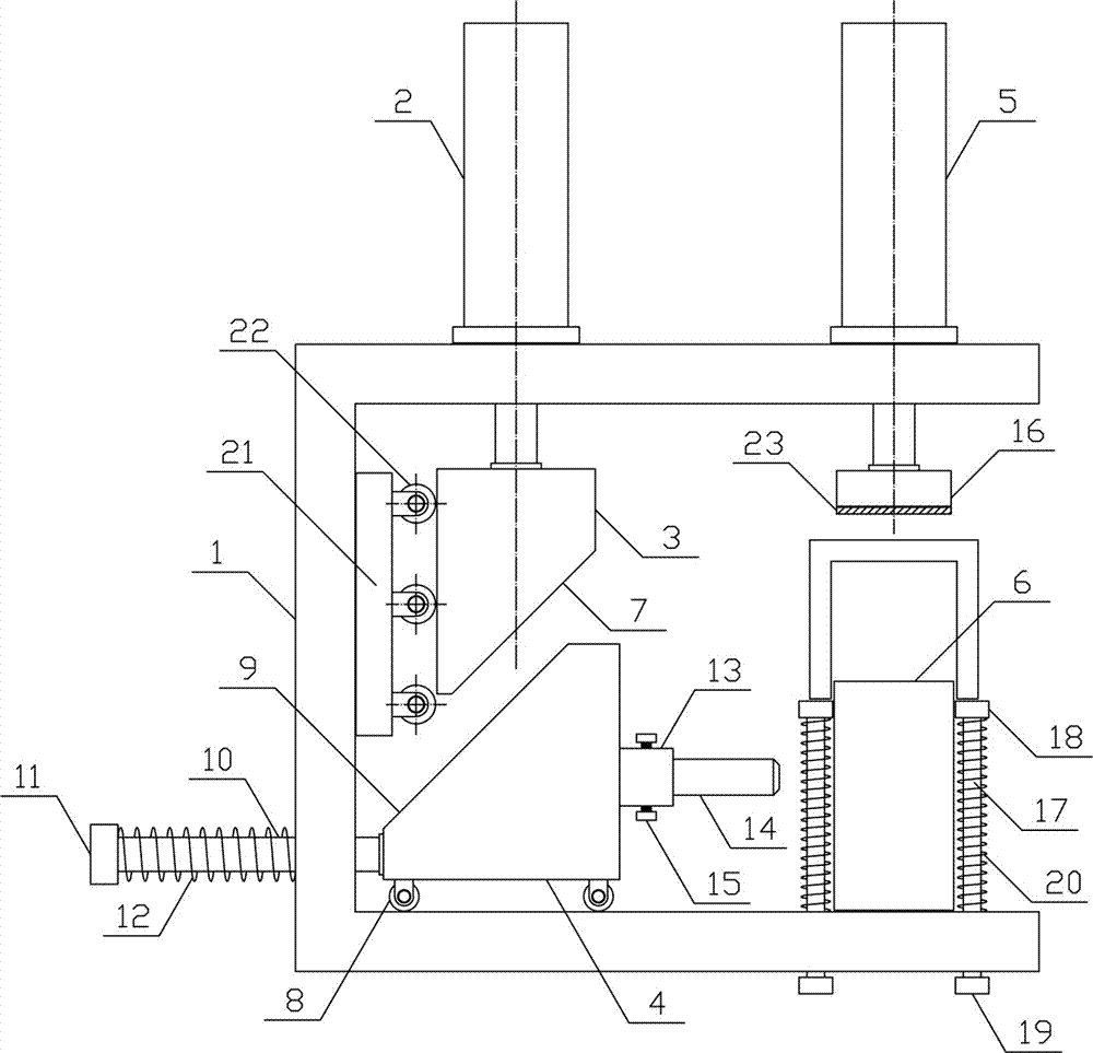
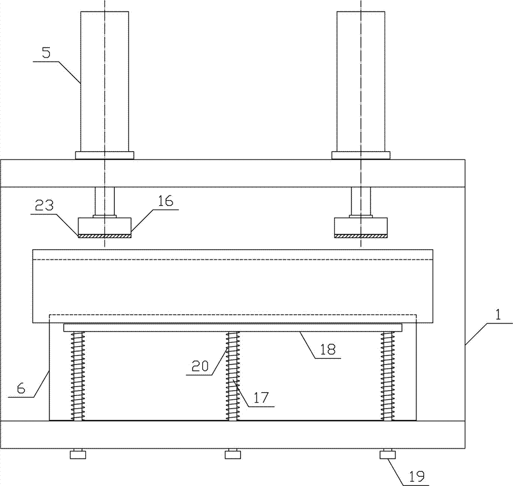
[0012] Such as figure 1 , figure 2 As shown, an aluminum punching mechanism of the present invention includes a fixed bracket 1, a punching cylinder 2, a lifting push plate 3, a translation punching plate 4, a pressing cylinder 5 and a material receiving bracket 6, and the side above the fixing bracket 1 The two ends are respectively provided with a punching cylinder 2 vertically downward, and the lifting push plate 3 is horizontally arranged at the output end of the punching cylinder 2, and the lower side of the lifting push plate 3 is provided with a first slope 7, and the fixed bracket on the lower side of the lifting push plate 3 1. ...


PUM


Abstract

The invention discloses an aluminum material punching mechanism, and belongs to the field of material processing mechanical equipment. The aluminum material punching mechanism comprises a fixed bracket, a punching air cylinder, a lifting pushing plate, a translation punching plate, a material pressing air cylinder and a material supporting bracket, wherein the lifting pushing plate is horizontally arranged at an output end of the punching air cylinder; the translation punching plate is horizontally arranged on the fixed bracket at the lower side of the lifting pushing plate; a plurality of translation guide rods are horizontally and uniformly arranged below one side of the translation punching plate; translation springs are arranged on the translation guide rods between a translation baffle block and the fixed bracket; a punching circular rod which is horizontally arranged is arranged in a mounting machine head; the output end of the material pressing air cylinder is horizontally equipped with the material pressing plate; the material supporting bracket is horizontally arranged on the fixed bracket at the lower side of the material pressing plate; and a lifting spring is arranged on a lifting guide rod at the upper side of the fixed bracket. The aluminum material punching mechanism disclosed by the invention is reasonable in structural design, and can be used for quickly and conveniently punching an aluminum material accurately and efficiently, so that punching efficiency and punching quality are improved, and producing processing needs are met.

Description

technical field [0001] The invention belongs to the field of material processing machinery and equipment, and in particular relates to an aluminum material punching mechanism, which is mainly used in the processing of aluminum profiles. Background technique [0002] Aluminum products made of aluminum and other alloying elements are usually processed into castings, forgings, foil plates, tubes, rods, etc., and then processed by cold bending, sawing, drilling, assembling, and coloring. The main metal element is aluminum, and some alloy elements are added to improve the performance of aluminum. Aluminum is a material that is standardized and mass-produced according to certain standards. This type of material has a certain appearance size and a certain cross-section shape. With certain mechanical and physical properties, aluminum can be used alone or further processed into other manufactured products. It is often used in building structures and manufacturing installations. In o...

Claims


Application Information

Patent Timeline
Patent Type & Authority Applications(China)
IPC IPC(8): B21D28/24B21D43/00B21D45/04
CPCB21D28/243B21D43/003B21D45/003
Inventor 张雅婷
Owner 张雅婷
Why Eureka
Try Eureka