
Open-end rotor spinning device

A rotor spinning, free-end technology, applied in the directions of free-end spinning machines, spinning machines, spinning machines with continuous winding, etc., can solve the problems of entry and insufficient sealing.

Active Publication Date: 2017-09-26
SAURER GERMANY GMBH & CO KG
View PDF16 Cites 2 Cited by
  • Summary
  • Abstract
  • Description
  • Claims
  • Application Information

AI Technical Summary

Problems solved by technology

[0023] The open-end rotor spinning device known from DE 197 29 192 A1, although widely used in the textile industry, also has the disadvantage that a sufficient seal cannot always be ensured between the channel plate adapter and the corresponding receptacle of the cover, resulting in air leakage Possibly accessible through the hole in the protrusion on the back of the channel plate adapter
This means that none of these known open-end rotor spinning devices can always reliably avoid contamination in the area of ​​the cover
[0024] In order to finally rule out the problem of air leakage into the rotor housing when using exchangeable channel plate adapters, an open-end rotor spinning device was developed which, although having the usual Rotor housing that can be under-pressurized and can be closed by a cover during spinning, but with a very special design of the channel plate adapter arranged in the receptacle of the cover

Method used


Image

  • Open-end rotor spinning device
  • Open-end rotor spinning device
  • Open-end rotor spinning device

Examples


Embodiment Construction

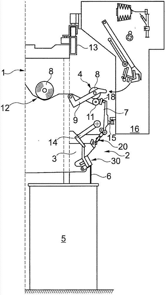
[0059] figure 1 Shown is a half side view of an open-end rotor spinning machine 1 . Such an open-end rotor spinning machine 1 generally has, as is known, a plurality of identical workstations 2 arranged side by side, expediently arranged on the front and rear of the textile machine.

[0060] Furthermore, these stations 2 are each equipped with an open-end rotor spinning device 3 and a winding device 4 .

[0061] During operation, in the open-end rotor spinning device 3, the fiber sliver 6 provided, for example, by the can 5 and prepared by the fiber sliver opening device 30 is spun into a yarn 7, and then the yarn is wound on the winding device 4 into a yarn 7. Cross-wind bobbin 8.

[0062] Such as figure 1 As shown, the winding device 4 is equipped with a creel 9 for rotating and holding an empty bobbin or a cross-wound bobbin 8, a bobbin drive roller 11 for frictionally driving the cross-wound bobbin 8, and a yarn reciprocating device 18 .

[0063] In this embodiment, e...


PUM


Abstract

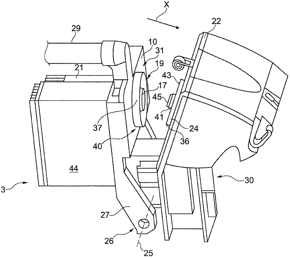
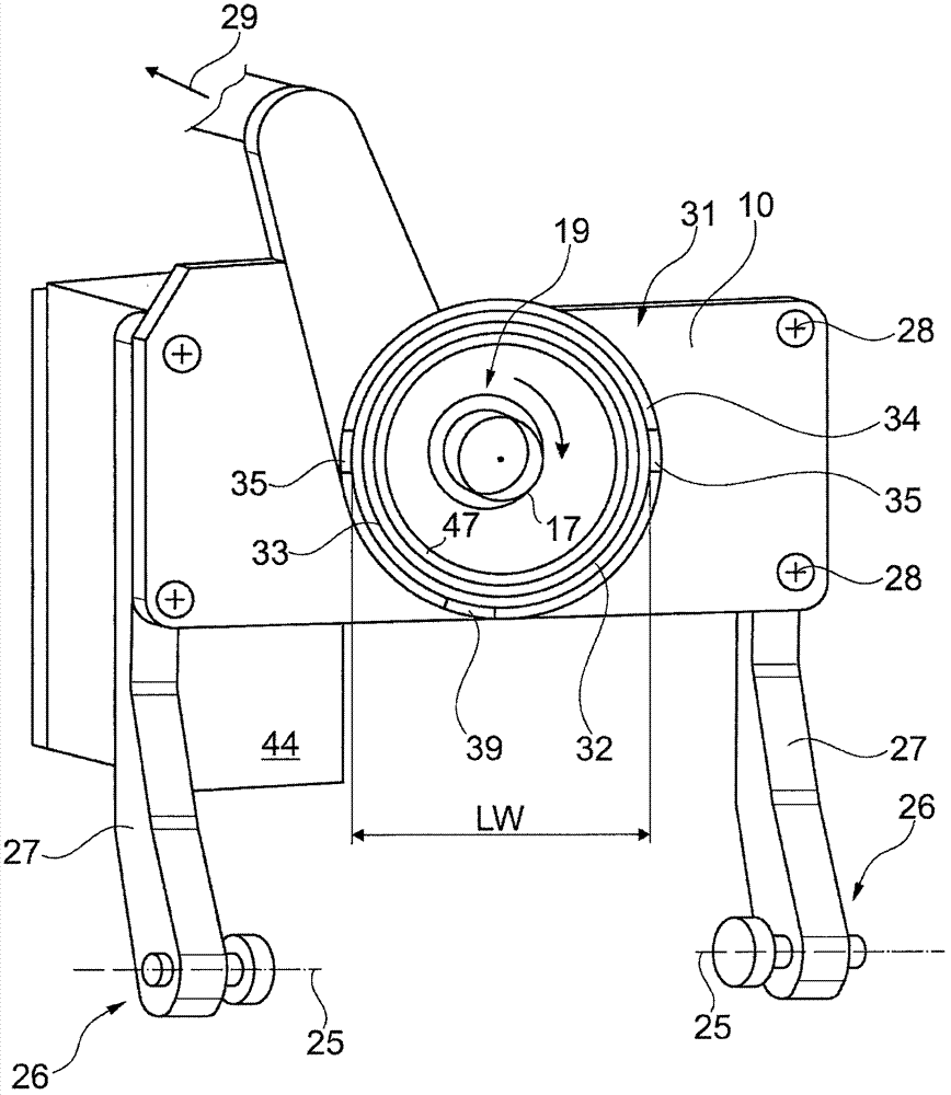
The invention relates to an open-end rotor spinning device (3) with a spinning rotor (19) which can be driven by a single motor, the rotor assembly (17) of which rotates in a rotor housing (10) which can be pressurized and which is driven by a drive (21) for the spinning rotor (19) and bearing arms (27) ) is connected to a cover element (22) having a fiber band dissolving device (30), and which comprises a part of a centering device (40), wherein the forwardly open rotor housing (10) is closed by the cover element (22) during the spinning process , which in turn has a receptacle (23) for a replaceably arranged channel plate adapter (24). According to the invention, the centering device (40) is formed by a guide surface (36) arranged on the channel plate adapter (24), as well as a guide device (31) arranged on the rotor housing (10), wherein the guide surface (36) arranged on the channel plate adapter (24) Closing state of the open-end rotor spinning device (3) in a form-fitting manner with the guide device (31) arranged on the rotor housing (10).

Description

technical field [0001] The invention relates to an open-end rotor spinning device with a rotor driven by a single motor, the rotor of which rotates in a rotor housing capable of applying a negative pressure, adjacent to the rotor housing is the drive for the rotor As well as the arm of the cover with the fiber sliver opening device, and the rotor cup housing has a part of the centering device (Zentriervorrichtung), the rotor cup housing that is opened forward is closed by the cover during spinning, said The cover in turn has a receptacle for an exchangeable channel plate adapter. Background technique [0002] Open-end rotor spinning installations, especially their production efficiency and the quality of the yarn produced, have improved considerably over time. In order to increase the production efficiency, for example, the rotational speed of the rotors has been increased above 100,000 revolutions per minute, mainly only by significantly reducing the spinning elements, esp...

Claims


Application Information

Patent Timeline
Patent Type & Authority Applications(China)
IPC IPC(8): D01H4/08D01H4/38
CPCD01H4/08D01H4/38
Inventor C·戈茨J·米奥德克海因茨-约瑟夫·波伊克L·温岑
Owner SAURER GERMANY GMBH & CO KG
Learn More