Check patentability & draft patents in minutes with Patsnap Eureka AI!

Crankcase ventilation system

A crankcase ventilation and crankcase technology, applied in crankcase ventilation, engine components, machines/engines, etc., can solve problems such as gas leakage, achieve the effects of preventing emulsification, reducing development costs, and reducing quantities

Inactive Publication Date: 2017-09-26
ANHUI JIANGHUAI AUTOMOBILE GRP CORP LTD
View PDF5 Cites 0 Cited by
  • Summary
  • Abstract
  • Description
  • Claims
  • Application Information

AI Technical Summary

Problems solved by technology

[0005] The purpose of the present invention is to provide a crankcase ventilation system to solve the above-mentioned problems in the prior art, eliminate gaseous water or gasoline remaining in the crankcase due to blow-by gas, prevent oil emulsification, and solve the problem of gas leakage at the same time problem, protect the atmosphere

Method used


Image

  • Crankcase ventilation system
  • Crankcase ventilation system
  • Crankcase ventilation system

Examples


Embodiment Construction

[0041] Embodiments of the present invention are described in detail below, examples of which are shown in the drawings, wherein the same or similar reference numerals designate the same or similar elements or elements having the same or similar functions throughout. The embodiments described below by referring to the figures are exemplary only for explaining the present invention and should not be construed as limiting the present invention.

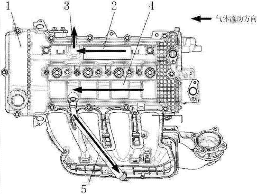
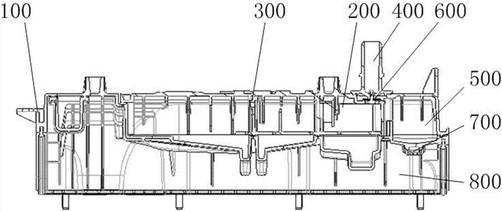
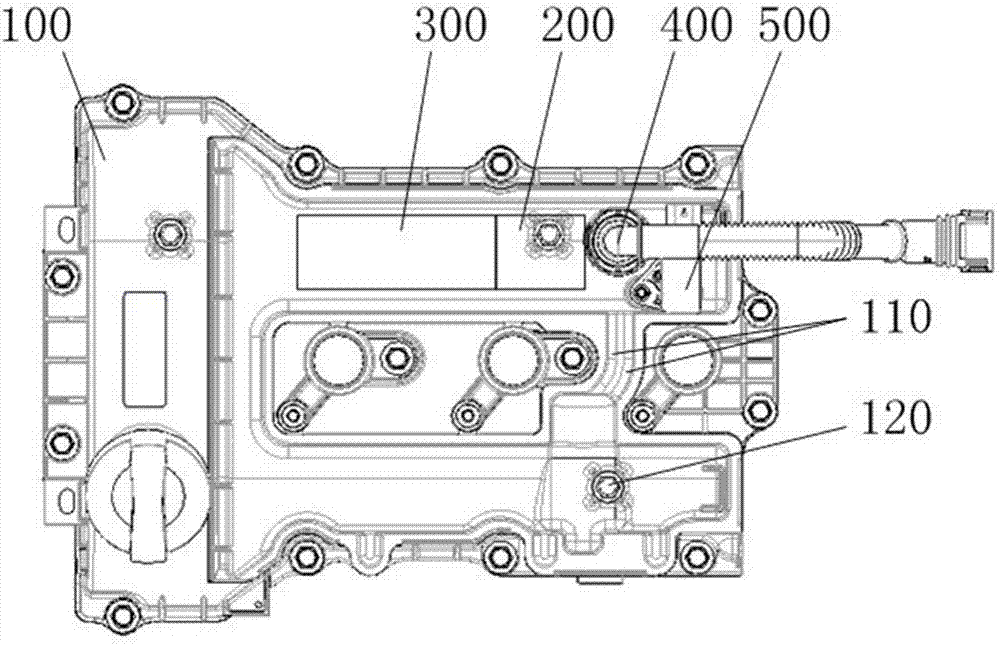
[0042] Please also refer to Figure 2 to Figure 5 , the embodiment of the present invention provides a crankcase ventilation system, which includes a first oil-air separator 200, a ventilation pipe 400, an air storage chamber 500, a first one-way valve 600 and a second one-way valve 700; wherein, the first The oil-gas separator 200 is fixedly arranged on the cylinder head shield 100; one end of the ventilation pipe 400 communicates with the first oil-gas separator 200, and the other end of the ventilation pipe 400 communicates with the r...


PUM


Abstract

The invention discloses a crankcase ventilation system. The crankcase ventilation system comprises a first oil-gas separator, a ventilation pipe, a gas storage cavity, a first one-way valve and a second one-way valve, wherein the first oil-gas separator is fixedly arranged on a cylinder cover shield; one end of the ventilation pipe communicates with the first oil-gas separator, and the other end of the ventilation pipe communicates with a breather; the air storage cavity is fixedly arranged on the cylinder cover shield and provided with a gas inlet and a gas outlet, the gas inlet communicates with the ventilation pipe, and the gas outlet communicates with a crankcase; the first one-way valve is fixedly arranged at the joint between the ventilation pipe and the first oil-gas separator; and the second one-way valve is fixedly arranged at the gas outlet. According to the crankcase ventilation system provided by the invention, only through one oil-gas separator, oil-gas separation requirements can be met when an engine works in the large load state or in the small load state; and the gas storage cavity is arranged and made to communicate with the ventilation pipe and the crankcase at the same time, thus, fresh air can be introduced, and gas in the crankcase can be cleaned through the fresh air.

Description

technical field [0001] The invention relates to the technical field of engines, in particular to a crankcase ventilation system. Background technique [0002] Determined by the characteristics of the engine, during the operation of the engine, due to the gap between the piston ring and the cylinder wall, it is inevitable that some gases will continuously escape from the combustion chamber into the crankcase of the engine. It will cause the gas pressure in the engine to gradually increase, resulting in oil seal damage, crankcase gas leakage and environmental pollution. Therefore, all engines need to be equipped with a crankcase ventilation system to guide this part of the exhaust gas out of the engine, and enter the cylinder through the intake manifold to be burned. But because the gas in the crankcase will carry a certain amount of engine oil, it is necessary to separate the engine oil from the mixed gas before passing it into the cylinder for combustion, which requires the...

Claims


Application Information

Patent Timeline
Patent Type & Authority Applications(China)
IPC IPC(8): F01M13/04F01M11/10
CPCF01M13/04F01M11/10F01M2013/0044F01M2250/00
Inventor 谢有路张应兵张建操陈亮朱浩杰刘彤罗亚伟董先瑜房程程苏晓芳徐鹏飞陈帆李欢王英杰陈尚尚王友成刘家宏
Owner ANHUI JIANGHUAI AUTOMOBILE GRP CORP LTD
Features
  • R&D
  • Intellectual Property
  • Life Sciences
  • Materials
  • Tech Scout
  • Unparalleled Data Quality
  • Higher Quality Content
  • 60% Fewer Hallucinations
Learn More