This helps you quickly interpret patents by identifying the three key elements:
Problems solved by technology
Method used
Benefits of technology
Problems solved by technology
[0004] In the torque limiter disclosed in Patent Document 1, when an overload exceeding a predetermined torque (predetermined torque) is applied when opening and closing the toilet seat or toilet lid, the engagement of the ratchet part is disengaged and the transmission of the overload is interrupted. , but there is a mechanical sound due to the rotation of the ratchet part
In addition, when the predetermined torque is set high to suppress the frequency of the mechanical sound, peripheral components such as motors and gears are required to have high strength in order to withstand an overload that does not exceed the predetermined torque. This also has an impact on the cost of the components
In addition, in the case of a resin ratchet, the torque (limit torque) when the transmission of the overload is actually disconnected has a large deviation, and the limit torque due to aging due to deformation of the ratchet itself during rotation is also considered. The change becomes bigger
[0005] The same problem occurs when the torque limiter is used to automatically open and close any movable animal other than the toilet seat.
Method used
Image
Click on the blue label to locate the original text in one second.
Reading with bidirectional positioning of images and text.
Examples
no. 1 approach
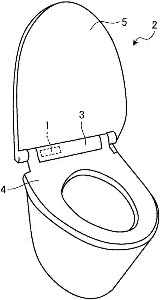
[0034] As a first embodiment of the present invention, a drive device including a torque limiter will be described. This drive device can be used in various devices, but the following description will be made with reference to an example of an opening and closing device applied to a toilet seat and lid that automatically opens and closes a toilet.
[0035] The drive unit 1 according to the first embodiment is arranged in the housing 3 of the toilet 2 with an electric toilet seat, and drives the toilet seat 4 and the lid 5 to open and close. Hereinafter, for ease of understanding, a drive unit that opens and closes the toilet seat 4 will be described as an example, but the lid 5 can also be opened and closed in the same manner.
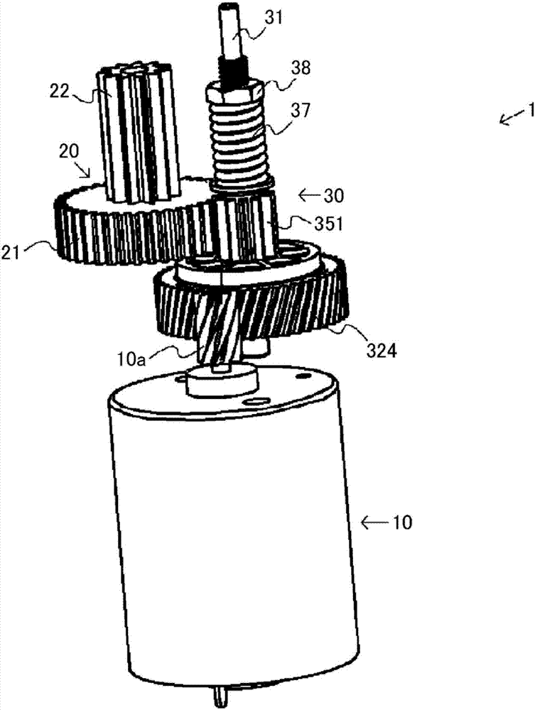
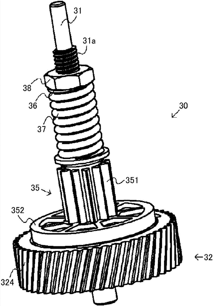
[0036] Such as figure 2 As shown, the drive unit 1 according to the first embodiment includes: a motor 10; a first gear portion 20 that transmits the rotational force generated by the motor 10 to the rotating shaft of the toilet seat 4 via a gear train, no...
no. 2 approach
[0095] In the drive unit 1 of the first embodiment, the toilet seat 4 is driven via the third gear portion 35 and the first gear portion 20. In addition, the second gear portion 32 is formed in a bottomed cylindrical shape. The friction plate 33 and the second friction plate 34 are accommodated, but these structures can also be changed and corrected arbitrarily.
[0096] Hereinafter, as an example, the first gear portion and the third gear portion are not used as constituent elements, but refer to Figure 7 ~ Figure 9 An example of a drive device in which the arrangement structure of the first friction plate and the second friction plate are different will be described.
[0097] Such as Figure 7 ~ Figure 9 As shown, the torque limiter 70 according to this embodiment includes a shaft 71, a first friction plate 33, a second friction plate 72, and a fourth gear portion 73.
[0098] Such as Picture 8 As shown, the shaft 71 has a D-shaped portion 711, a cylindrical portion 712, and a ...
PUM
Abstract
A torque limiter comprising a first rotary element rotated by a drive source, a first frictional element interlocked with the first rotary element, a second frictional element disposed overlapping the first frictional element and rotated along with the rotation of the first frictional element by the frictional force with the first frictional element, and a second rotary element interlocked with the second frictional element. Preferably, the first rotary element and the second rotary element are rotatably supported on the same rotating shaft, either one of the first rotary element and the second rotary element is fixed on the rotating shaft, and the other is supported to be capable of rotating relative to the rotating shaft.
Description
Technical field [0001] The present invention relates to a torque limiter and a drive device. Background technique [0002] Circulates toilets with electric toilet seat and toilet lid opening and closing functions equipped with a drive unit that automatically opens and closes the toilet seat or toilet lid. Such a drive unit is equipped with a torque limiter for protecting gears and motors constituting the drive unit when an overload is applied to the toilet seat or the toilet seat when a person opens and closes the toilet seat or the toilet lid by hand. As a torque limiter, a torque limiter using a ratchet is proposed (refer to Patent Document 1). [0003] Patent Document 1: Japanese Patent Application Publication No. 2014-149013 [0004] In the torque limiter disclosed in Patent Document 1, if an overload exceeding a predetermined torque (predetermined torque) is applied when opening and closing the toilet seat or the toilet lid, the engagement of the ratchet part is deviated and t...
Claims
Application Information
Patent Timeline
Application Date:The date an application was filed.
Publication Date:The date a patent or application was officially published.
First Publication Date:The earliest publication date of a patent with the same application number.
Issue Date:Publication date of the patent grant document.
PCT Entry Date:The Entry date of PCT National Phase.
Estimated Expiry Date:The statutory expiry date of a patent right according to the Patent Law, and it is the longest term of protection that the patent right can achieve without the termination of the patent right due to other reasons(Term extension factor has been taken into account ).
Invalid Date:Actual expiry date is based on effective date or publication date of legal transaction data of invalid patent.

