Washing and soaking device for combustion jet of gas furnace

A technology for burning nozzles and gas furnaces, which is applied in the directions of cleaning hollow objects, cleaning methods and utensils, chemical instruments and methods, etc., can solve the problems of troublesome arrangement, low soaking efficiency, high cost, etc., so as to improve soaking efficiency, easy to Promotion, low cost effect

Pending Publication Date: 2017-09-29
徐州东方热电有限公司
View PDF26 Cites 4 Cited by
  • Summary
  • Abstract
  • Description
  • Claims
  • Application Information

AI Technical Summary

Problems solved by technology

[0002] At present, after the combustion nozzles of gas furnaces in power plants have been used for a period of time, due to insufficient combustion and other reasons, the channels in the nozzles will be blocked. Since the combustion nozzles of gas furnaces are key equipment, they directly affect the work of gas furnaces. Cleaning is performed from time to time, and because the combustion nozzles of gas furnaces in power plants are expensive precision equipment with complex structures, existing vibration cleaning machines are not applicable. Therefore, at present, domestic power plants send gas furnace combustion nozzles to In foreign countries, foreign suppliers are invited to clean. The cost of one cleaning is expensive. The cost of cleaning the combustion nozzle of a single gas furnace is between 30,000 and 35,000. Each gas furnace has a group of 21, and the average cleaning cycle is 45 days, which takes a year. About 8 times of cleaning, the cost of one cleaning is about 700,000, and the annual cleaning cost is nearly 6 million, which greatly affects the normal operation and profit of the gas furnace in the power plant, and the cleaning cycle of each group of gas furnace combustion nozzles, In some places where the pollution is serious, the cycle is shortened to an average of 30 days, or even shorter, and each channel in the nozzle will be blocked, so the maintenance cost of the nozzle is extremely high
The current market price for replacing the gas furnace combustion nozzle is about 70,000 yuan, and a group of 21 needs about 1.5 million yuan, which greatly increases the operating cost of the power plant. At present, in China, no manufacturer has the ability to clean this gas furnace combustion nozzle The technical strength of the nozzle is subject to foreign suppliers. In order not to affect production and operation, many power plants will choose to directly purchase new combustion nozzles.
After more than 3 years of research and development, our factory technicians have initially possessed the technical ability to clean this nozzle. The cleaning steps include pre-soaking the nozzle before cleaning. The current soaking method used in our factory is to directly put the combustion nozzle into the In the container, the combustion nozzles are stacked up and down, and then the soaking liquid is injected into the container for soaking. However, when soaking in this method, the soaking liquid is in a static state, the penetration is slow, and the soaking efficiency is low. When the pipe is blocked by carbon deposits, the static soaking liquid It is difficult to break through. The operator will manually swing the burning nozzle in the soaking liquid to make the soaking liquid flow in the burning nozzle to speed up the soaking efficiency. However, due to the corrosiveness of the soaking liquid, it will cause damage to human skin, and the stacked arrangement in the up and down direction The method is very troublesome, inefficient, and poor in effect when performing operations such as flipping

Method used


Image

  • Washing and soaking device for combustion jet of gas furnace

Examples


Embodiment Construction

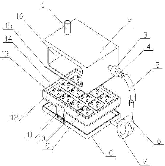
[0013] A gas furnace combustion nozzle cleaning and soaking device of the present invention is realized in this way. When in use, there are four passages in the combustion nozzle, including a spare passage. It is necessary to clean the three passages used. When the nozzle is soaked, First, place the removed nozzles on multiple magnetic plates (14) one by one, and the magnetic plates (14) will absorb the nozzles, and make the three channels to be cleaned on the nozzles and the three channels on the magnetic plates (14) The hollow connectors (9) are connected in one-to-one correspondence, cover the box cover, and fix it with the locking buckle (11), inject the soaking liquid into the middle tray (13) through the liquid injection pipe (1), and the soaking liquid flows into the middle tray (13), and then soak the nozzle on the magnetic plate (14), the soaking liquid flows into the three channels in the nozzle, and soaks the blockages such as carbon deposits in the three channels, m...


PUM


Abstract

The invention discloses a device for soaking a jet through circular flowing of a soaking solution. The device is characterized in that an intermediate tray is positioned in a liquid storing bottom plate, wherein a groove is formed in the side edge of the bottom surface of the inner side of the intermediate tray; the depth of the groove is less than the thickness of a sealing strip, and the groove is slightly wider than the sealing strip; a fluff layer is positioned at the bottom part of the liquid storing bottom plate, and a limiting boss is positioned at the upper side edge of the liquid storing bottom plate; the sealing strip is positioned at the lower side edge of the intermediate tray; a plurality of magnetic plates which are permanents and distributed to form a rectangular array are uniformly positioned in the intermediate tray; three hollow connectors are arranged in a triangle form on the magnetic plates and correspondingly communicate with the liquid storing bottom plate; a box cover is positioned on the liquid storing bottom plate by connecting through a locking buckle; an observing window is arranged in the box cover; one end of a liquid filling pipe is positioned on the box cover and communicates with the intermediate tray.

Description

technical field [0001] The invention relates to a cleaning and soaking device for a combustion nozzle of a gas furnace, relates to a device for soaking the combustion nozzle of a gas furnace before cleaning, and belongs to the field of power plant equipment. In particular, it relates to a device for immersing nozzles through circulating flow of immersion liquid. Background technique [0002] At present, after the combustion nozzles of gas furnaces in power plants have been used for a period of time, due to insufficient combustion and other reasons, the channels in the nozzles will be blocked. Since the combustion nozzles of gas furnaces are key equipment, they directly affect the work of gas furnaces. Cleaning is performed from time to time, and because the combustion nozzles of gas furnaces in power plants are expensive precision equipment with complex structures, existing vibration cleaning machines are not applicable. Therefore, at present, domestic power plants send gas ...

Claims


Application Information

Patent Timeline
Patent Type & Authority Applications(China)
IPC IPC(8): B08B9/032B08B9/027
CPCB08B9/027B08B9/0323
Inventor 张立新姜建琪扈军赵昕
Owner 徐州东方热电有限公司
Why Eureka
Try Eureka