
A mold oil injection mechanism and its stamping die

A technology of molds and oil injection pipes, which is applied in the field of stamping equipment, can solve the problems of affecting production efficiency, time-consuming and laborious oiling, etc., and achieve the effect of improving efficiency and simple mechanism structure

Active Publication Date: 2019-04-16
ANHUI JIANGHUAI AUTOMOBILE GRP CORP LTD
View PDF8 Cites 0 Cited by
  • Summary
  • Abstract
  • Description
  • Claims
  • Application Information

AI Technical Summary

Problems solved by technology

[0002] During the production process of the stamping die, due to the product structure, some dies need to be oiled during production, usually manually. If the plate is large, oiling is time-consuming and labor-intensive, which affects production efficiency

Method used


Image

  • A mold oil injection mechanism and its stamping die
  • A mold oil injection mechanism and its stamping die
  • A mold oil injection mechanism and its stamping die

Examples


Embodiment Construction

[0019] Embodiments of the present invention are described in detail below, and examples of the embodiments are shown in the drawings, wherein the same or similar reference numerals denote the same or similar elements or elements having the same or similar functions throughout. The embodiments described below by referring to the figures are exemplary only for explaining the present invention and should not be construed as limiting the present invention.

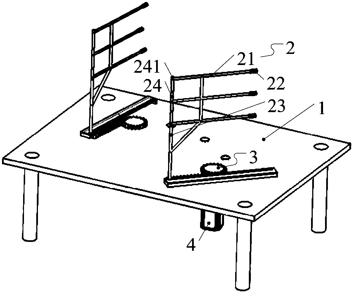
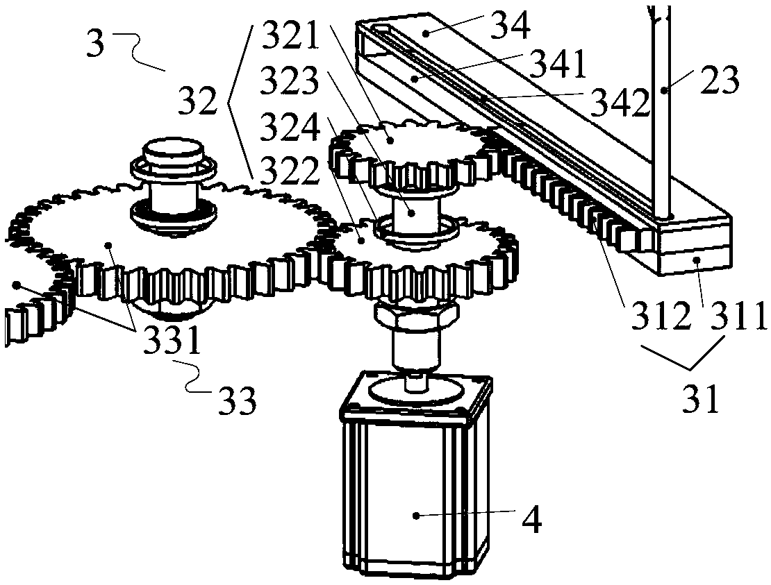
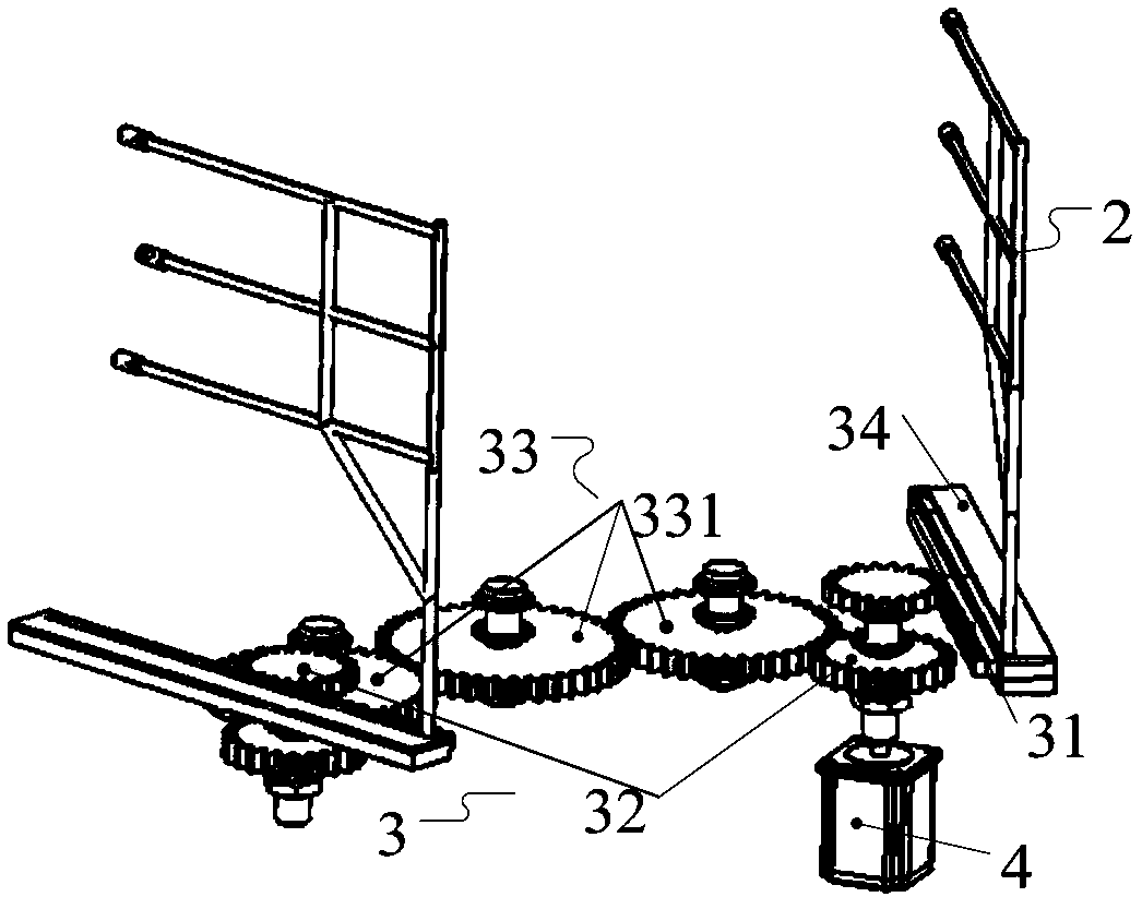
[0020] Such as Figure 1 to Figure 3 As shown, the embodiment of the present invention provides a mold oil injection mechanism, which includes: a mounting table 1, an oil injection bracket 2, a transmission device 3 and a motor 4, and the mounting table 1 is provided with a chute and a through hole. The fuel injection bracket 2 includes: a fuel injection pipe 21, a nozzle 22 and a bracket 23, one side port of the fuel injection pipe 21 is fixedly connected with the nozzle 22, and the other side port of the fuel injection pipe ...


PUM


Abstract

The invention discloses a die oil-blowout mechanism and a stamping die thereof. The die oil-blowout mechanism comprises a mounting table, an oil-blowout support, a transmission device and a motor. The transmission device comprises a rack, a compound gear and a transition gear set, the compound gear comprises an upper layer gear, a lower layer gear and a connecting shaft, and the connecting shaft connects the upper layer gear with the lower layer gear; and the upper layer gear is connected with the rack in an engaged mode, and the lower layer gear is connected with the transition gear set in an engaged mode. The motor drives the compound gear to rotate in the using process, the compound gear drives the rack and the transition gear set to move and drives the oil-blowout support to move, after the position is reached, drawing oil is blown out, and automatic oil-blowout is achieved. After the automatic oil-blowout is completed, the motor reversely drives the compound gear to rotate, and the oil-blowout support is driven to return back to the original position. According to the die oil-blowout mechanism, the structure is simple, automatic oil-blowout can be achieved, and the oil-blowout efficiency is improved. The invention further provides a stamping die including the die oil-blowout mechanism, the problem that oil needs to be smeared on workpieces manually is solved, and the quality of the stamped workpieces is improved.

Description

technical field [0001] The invention relates to stamping equipment, in particular to a mold oil injection mechanism and a stamping mold thereof. Background technique [0002] During the production process of the stamping die, due to the product structure, some dies need to be oiled during production, usually manually. If the plate is large, oiling is time-consuming and labor-intensive, which affects production efficiency. Contents of the invention [0003] The object of the present invention is to provide a mold oil injection mechanism and its stamping die, which can realize automatic oil injection and improve the efficiency of oil injection. [0004] In order to achieve the above object, the present invention provides a mold oil injection mechanism, which includes: a mounting table, a transmission device, an oil injection bracket and a motor, and the mounting table is provided with a chute and a through hole; the transmission device includes: Rack, composite gear and tra...

Claims


Application Information

Patent Timeline
Patent Type & Authority Patents(China)
IPC IPC(8): B21D37/18B21D37/10
CPCB21D37/10B21D37/18
Inventor 何成周晶晶杜长胜佘威汪军顾绪功
Owner ANHUI JIANGHUAI AUTOMOBILE GRP CORP LTD
Learn More