
Double-oil-tank communicating structure for automobiles

A dual fuel tank, automobile technology, applied in vehicle components, layout combined with internal combustion engine fuel supply, power plant and other directions, can solve the problems of splash collision, blockage, small ground clearance, etc., and achieves simple structure principle, convenient use, Not easy to be blocked

Pending Publication Date: 2017-09-29
JIANGLING MOTORS
View PDF18 Cites 0 Cited by
  • Summary
  • Abstract
  • Description
  • Claims
  • Application Information

AI Technical Summary

Problems solved by technology

According to its principle and layout, this single communication pipe structure has the following problems: 1. With the help of natural action and no external power input, the fuel supply state between the two fuel tanks is unstable, and it cannot ensure that the fuel in the auxiliary fuel tank can replenish the main fuel tank in time ; 2. The connecting pipe is arranged at the bottom of the fuel tank. Considering the strength of the fuel tank, the inner diameter of the connecting pipe should not be too large, the flow is limited and it is easy to be blocked by impurities in the oil; 3. The connecting pipe is arranged at the bottom of the fuel tank, which is almost the lowest coordinate of the whole vehicle. The ground clearance is small, and it is easy to be hit by splashes, which poses a safety risk; 4. When refueling, the main and auxiliary fuel tanks communicate with each other, and the two fuel tanks cannot be completely filled with fuel

Method used


Image

  • Double-oil-tank communicating structure for automobiles
  • Double-oil-tank communicating structure for automobiles

Examples


Embodiment

[0023] Example: see figure 1 -2.

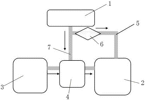
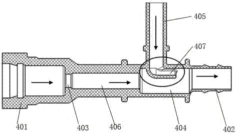
[0024] The invention discloses a communication structure of two fuel tanks of an automobile, which comprises an engine 1, a main fuel tank 2 and an auxiliary fuel tank 3. 1. The main fuel tank 2 and the auxiliary fuel tank 3 are connected through the three-way valve 4. The outside of the three-way valve 4 is in an inverted T shape. The upper vertical section 405 of the three-way valve 4 is connected with the main oil return pipeline 1 of the low-pressure oil circuit of the engine chassis. One end of the branch pipes on both sides of the bottom of the three-way valve 4 is a large end 401, and the other end is a small end 402. The large end 401 communicates with the auxiliary fuel tank 3, and the small end 402 communicates with the main fuel tank 2. The cross section of the large end 401 The area is greater than the cross-sectional area of ​​the small end 402. A throat 403 and a diffuser section are also arranged between the large end 401 and ...


PUM


Abstract

The invention relates to a double-oil-tank communicating structure for automobiles. The structure comprises an engine, a main oil tank and an auxiliary oil tank which are connected through a three-way valve, wherein the three-way valve is externally formed with an inverted-T shape, and the vertical section of the upper part of the three-way valve is communicated with the main oil-return pipeline of the low pressure oil circuit of the chassis of the engine; the end of one of branch pipes on both sides of the bottom of the three-way valve is a big end, and the end of the other of the branch pipes is a small end; the big end and a lower end are communicated with the main oil tank and the auxiliary oil tank respectively, and a choke and a diffusion section are successively arranged between the big end and the small end; the lower end of the vertical section is communicated with the diffusion section, and the cross-sectional area of the vertical section is smaller than the cross-sectional area of the diffusion section located directly below the vertical section; the bottom of the vertical section is provided with a horizontal contraction section which is inserted into the diffusion section, the oil outlet of the contraction section is positioned in the diffusion section and faces the direction of the main oil tank, and the cross-sectional area of the contraction section is smaller than the cross-sectional area of the vertical section. The double-oil-tank communicating structure for the automobiles uses a Venturi effect, when the engine works with oil return, the three-way valve produces the Venturi effect, and the oil is actively input into the main oil tank.

Description

technical field [0001] The invention relates to the technical field of automobile fuel supply systems, in particular to an automobile double fuel tank communication structure. Background technique [0002] The capacity of the fuel tank directly determines the endurance of the car. For cars with the same engine, the bigger the fuel tank, the farther it can run. With the rapid development of the current logistics industry, it has become a trend to equip vehicles with large-volume fuel tanks. However, large fuel tanks have high requirements for layout space. The double fuel tank design overcomes the space limitation on one side of the vehicle and can make full and reasonable use of the limited space on both sides of the vehicle. The large volume can avoid the impact of fuel price differences in different regions on logistics costs. Since the double fuel tanks are arranged on the left and right sides of the frame, the connection between the two fuel tanks becomes the key to eff...

Claims


Application Information

Patent Timeline
IPC IPC(8): B60K15/01B60K15/077
CPCB60K15/01B60K15/077
Inventor 徐燕茹温永钢韩跃斌李鹏
Owner JIANGLING MOTORS
Learn More