An Acceleration-Activated Continuous Girder Bridge Strut Damping Device

A shock absorbing device and acceleration technology, applied in bridges, bridge construction, bridge parts, etc., can solve the problems of unfavorable continuous girder bridge seismic performance, difficult energy consumption shock absorption, increased seismic response, etc., to achieve good continuous energy consumption capacity and Safety, good elasticity, effect of reducing seismic response

Active Publication Date: 2018-10-12
SHIJIAZHUANG TIEDAO UNIV
View PDF6 Cites 0 Cited by
  • Summary
  • Abstract
  • Description
  • Claims
  • Application Information

AI Technical Summary

Problems solved by technology

The Lock-up device uses the relative motion speed of the beam and pier as an index to determine the timing of locking. In theory, it can realize the coordinated force of each pier, but its high cost and complicated maintenance in the later period make its application less
Although some existing inventive devices can realize the locking function of the movable pier and the girder body and reduce the seismic response of the fixed pier and the girder body, due to the fixed connection stiffness, when the movable pier and the girder body are locked, the natural vibration period of the whole bridge will be shortened As a result, the overall seismic response of the whole bridge increases. In addition, due to the structural characteristics and the limitation of the mechanism, there is a gap in the existing locking device. Increasing the overall seismic response to a certain extent is not conducive to maximizing the aseismic performance of continuous girder bridges, and it is not easy to achieve energy dissipation and shock absorption

Method used


Image

  • An Acceleration-Activated Continuous Girder Bridge Strut Damping Device
  • An Acceleration-Activated Continuous Girder Bridge Strut Damping Device
  • An Acceleration-Activated Continuous Girder Bridge Strut Damping Device

Examples


Embodiment Construction

[0035] In order to make the object, technical scheme and advantages of the present invention clearer, the following in conjunction with the attached Figure 1-9 The present invention is clearly and completely described with reference to specific examples.

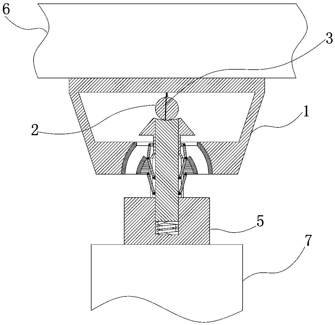
[0036] as attached figure 1 As shown, the present invention includes a casing 1, a support device and a load-bearing platform 5; the casing 1 is fixedly installed on the bottom of the beam body 6; the load-bearing platform 5 is fixedly installed on the top of the movable pier 7; Between the box 1 and the load-bearing platform 5; the support device includes a sleeve 401, a support column 405 installed in the sleeve 401 and capable of moving up and down along the inner wall of the sleeve 401, and a ring uniformly installed on the sleeve 401 and the support column 405 More than two hinge devices on the top can well resist the horizontal earthquake load in all directions; the activation ball 2 is set on the top of the sleeve 4...


PUM


Abstract

The invention relates to an acceleration-activated continuous beam bridge strut damping device, which comprises a sleeve box, a support device and a load-bearing platform; the sleeve box is installed at the bottom of the beam body; the load-bearing platform is installed at the top of a movable pier; the support device is installed on the sleeve box between the bearing platform and the bearing platform; the supporting device includes a sleeve, a supporting column and more than two hinge devices; an activation ball is arranged on the top of the sleeve and the supporting column; the supporting column is arranged in the bearing platform, and a compression spring is installed at the bottom of the supporting column; The invention has good deformation coordination ability. When the contact force between the polyurethane rubber sheets is too large, the hinged connection shrinks inward, and the supporting column descends to press the compression spring; when the contact force between the polyurethane rubber sheets decreases, the compression spring will support The column jacks up, and the hinge device expands outwards, so that good elastic contact between the polyurethane rubber sheets is always maintained; the invention has strong environmental adaptability, simple maintenance and strong environmental adaptability.

Description

technical field [0001] The invention relates to an acceleration-activated continuous girder bridge strut damping device, which belongs to the field of bridge shock absorption and isolation, and is suitable for the new anti-seismic design of highway bridges, railway bridges, urban bridges and various large continuous girder structures and the anti-seismic design of existing buildings reinforcement. Background technique [0002] In current highway bridges, railway bridges, urban bridges and various large-scale continuous beam structures, in order to meet the displacement requirements caused by temperature loads, each link of continuous beam bridges is often provided with only one fixed pier, which not only makes the seismic capacity of the fixed pier difficult It meets the seismic requirements, and also makes the longitudinal seismic displacement response of continuous girder bridges larger, which can easily cause damage to expansion joints and supports, and even lead to sever...

Claims


Application Information

Patent Timeline
Patent Type & Authority Patents(China)
IPC IPC(8): E01D19/00
CPCE01D19/00
Inventor 陈士通李锋沈英明逯久喜张耀辉孙志星王海林
Owner SHIJIAZHUANG TIEDAO UNIV
Why Eureka
Try Eureka