Anti-explosion waterproof breathable valve

A waterproof breathable valve, waterproof breathable membrane technology, applied in the direction of safety valve, balance valve, valve device, etc., can solve the problems of high product maintenance cost and replacement difficulty, users can not detect in time, membrane leakage and other problems

Inactive Publication Date: 2017-09-29
惠州市华兴科技有限公司
View PDF0 Cites 3 Cited by
  • Summary
  • Abstract
  • Description
  • Claims
  • Application Information

AI Technical Summary

Problems solved by technology

But this method also brings other hidden dangers in the process of solving explosion-proof
First, one-time puncture is adopted. Although the product is prevented from blasting, the punctured diaphragm has water leakage and needs to be replaced in time. The product maintenance cost and replacement difficulty are relatively high; second,

Method used


Image

  • Anti-explosion waterproof breathable valve
  • Anti-explosion waterproof breathable valve
  • Anti-explosion waterproof breathable valve

Examples


Embodiment 1

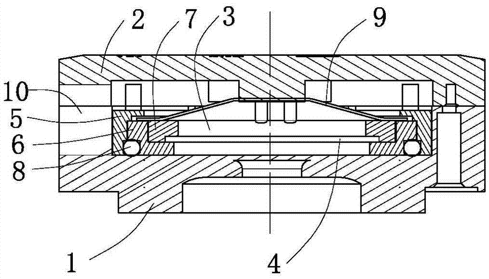
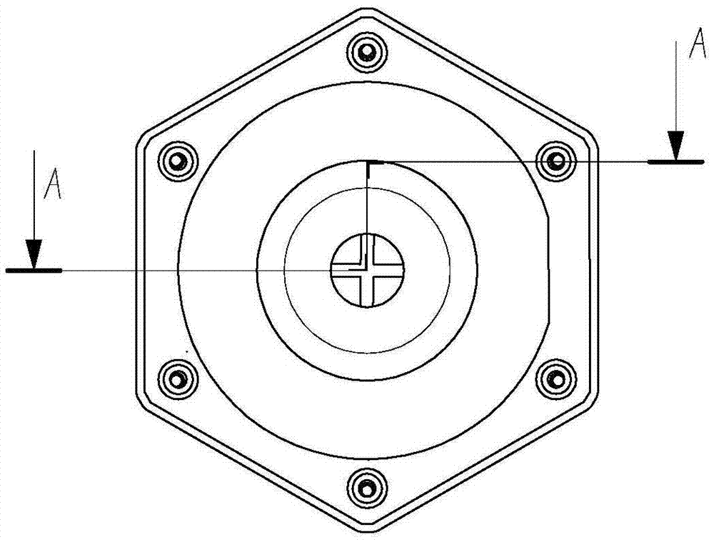
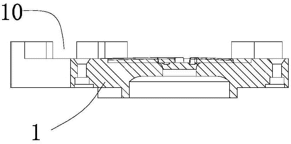
[0019] Example 1: Please refer to figure 1 , figure 2 and image 3 , The explosion-proof, waterproof and breathable valve disclosed in this embodiment includes a valve body 1 and a cover 2 buckled on the valve body 1. The buckling of the valve body 1 and the cover 2 forms a cavity 3 inside, in which a cavity 3 is formed. The waterproof and breathable membrane 4 separates the chamber into an inner chamber communicating with the inside of the device and an outer chamber communicating with the outside. The valve body 1 is docked with the corresponding equipment, and the valve body 1 can be provided with a screw interface, which can be fixed with the equipment through threads (bolts or flange structure can also be used to fix the valve body on the equipment), so that the valve body 1 is fixed on On the equipment casing (not shown in the figure), a through hole is opened at the bottom of the valve body 1 to communicate with the inside of the equipment.

[0020] A slidable sliding rin...

Embodiment 2

[0030] As attached Figure 4 , Figure 5 Shown. For the explosion-proof, waterproof and breathable valve disclosed in this embodiment, the difference between this embodiment and the first embodiment is that the pressure relief hole 10 is provided with the end of the cover 2 and the outer end of the cover 2 is provided with an outwardly extending pipe joint 11. It is convenient to connect external pipes. In this structure, in order to obtain instant release when the internal pressure of the equipment exceeds a safe value, a ventilation channel 51 is provided on the outer wall of the main ring 5. When the equipment pressure exceeds the safe value, the sliding ring assembly, waterproof rubber ring 8 and waterproof The breathable membrane 4 moves toward the outer chamber under the action of the internal pressure of the device, the waterproof rubber ring 8 is separated from the inner end surface of the valve body 1, and the inside of the device passes through the gap between the en...


PUM


Abstract

The invention relates to an explosion-proof, waterproof and breathable valve, which comprises a valve body, a cover body, a waterproof and breathable film, and an elastic dome. A sliding ring assembly is set in the chamber, and a pressure relief hole is arranged on the side wall of the valve body or the cover body. , a waterproof rubber ring is fixed on the end face of the sliding ring assembly. The waterproof and gas-permeable membrane of the present invention will not be punctured, and the waterproof and gas-permeable membrane returns to a normal state after the excessive internal pressure is released. At the same time, since the dome is used as the elastic part for the position restoration of the internal components, the sensitivity and smoothness of the waterproof and breathable membrane, the main ring, the pressure ring and the inner ring in the process of moving outwards under the pressure of the internal pressure of the equipment are improved, ensuring The inside of the device and the pressure relief hole can be accurately connected to realize the release of pressure, which is safer and more reliable. The entire valve can be designed to be thinner and smaller, and it is more convenient to apply to equipment with limited installation space and high installation requirements.

Description

Technical field [0001] The invention relates to the field of explosion-proof, waterproof and breathable, in particular to an explosion-proof, waterproof and breathable valve. Background technique [0002] At present, in the fields of vehicle batteries, solar energy, and new energy on the market, most of them use a one-time piercing of the waterproof, breathable and explosion-proof membrane to release the gas in the internal space to achieve the effect of explosion protection. But this method also brings other hidden dangers in the process of solving explosion protection. First, the use of a one-time puncture prevents the product from blasting, but the diaphragm after the puncture has water leakage and needs to be replaced in time. The maintenance cost and difficulty of the product are relatively high; second, the product releases internal space gas, which needs to reach A certain pressure will pierce the diaphragm, which will result in greater pressure but not reaching the punct...

Claims


Application Information

Patent Timeline
IPC IPC(8): F16K17/04F16K17/164F16K24/04
CPCF16K17/0493F16K17/164F16K24/04
Inventor 王永球李耀华游鲜红王义心
Owner 惠州市华兴科技有限公司
Why Eureka
Try Eureka