
Extension rod for injection needle valve for ap1000 reactor type nuclear power unit

A technology of nuclear power units and extension rods, which is applied in the direction of valve details, valve devices, mechanical equipment, etc., can solve the problems of operators' physical health risks, tight operating space, and affecting the physical and mental health of operators, so as to avoid radiation threats and increase The effect of manipulating space and protecting physical and mental health

Active Publication Date: 2019-05-24
江苏华洋新思路能源装备股份有限公司
View PDF10 Cites 0 Cited by
  • Summary
  • Abstract
  • Description
  • Claims
  • Application Information

AI Technical Summary

Problems solved by technology

[0002] The injection needle valve for AP1000 reactor nuclear power unit is installed in the area with heavy nuclear radiation, and the operating space is very tight. At the same time, due to the frequent operation of the injection needle valve, if the personnel directly operate it, the operator will be threatened by radiation. It will cause great danger to the physical health of the operator, which will inevitably affect the physical and mental health of the operator. Therefore, we were invited by the nuclear power plant to design a technical solution to this technical problem

Method used


Image

  • Extension rod for injection needle valve for ap1000 reactor type nuclear power unit
  • Extension rod for injection needle valve for ap1000 reactor type nuclear power unit
  • Extension rod for injection needle valve for ap1000 reactor type nuclear power unit

Examples


Embodiment Construction

[0025] The present invention will be described in detail below in conjunction with the accompanying drawings and embodiments.

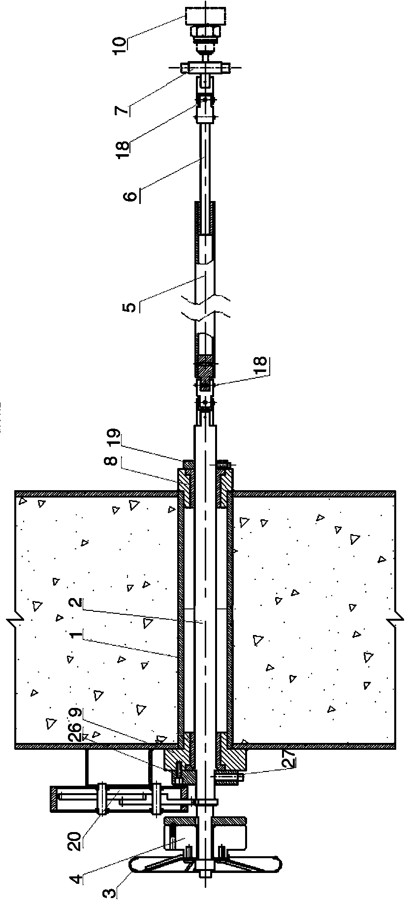
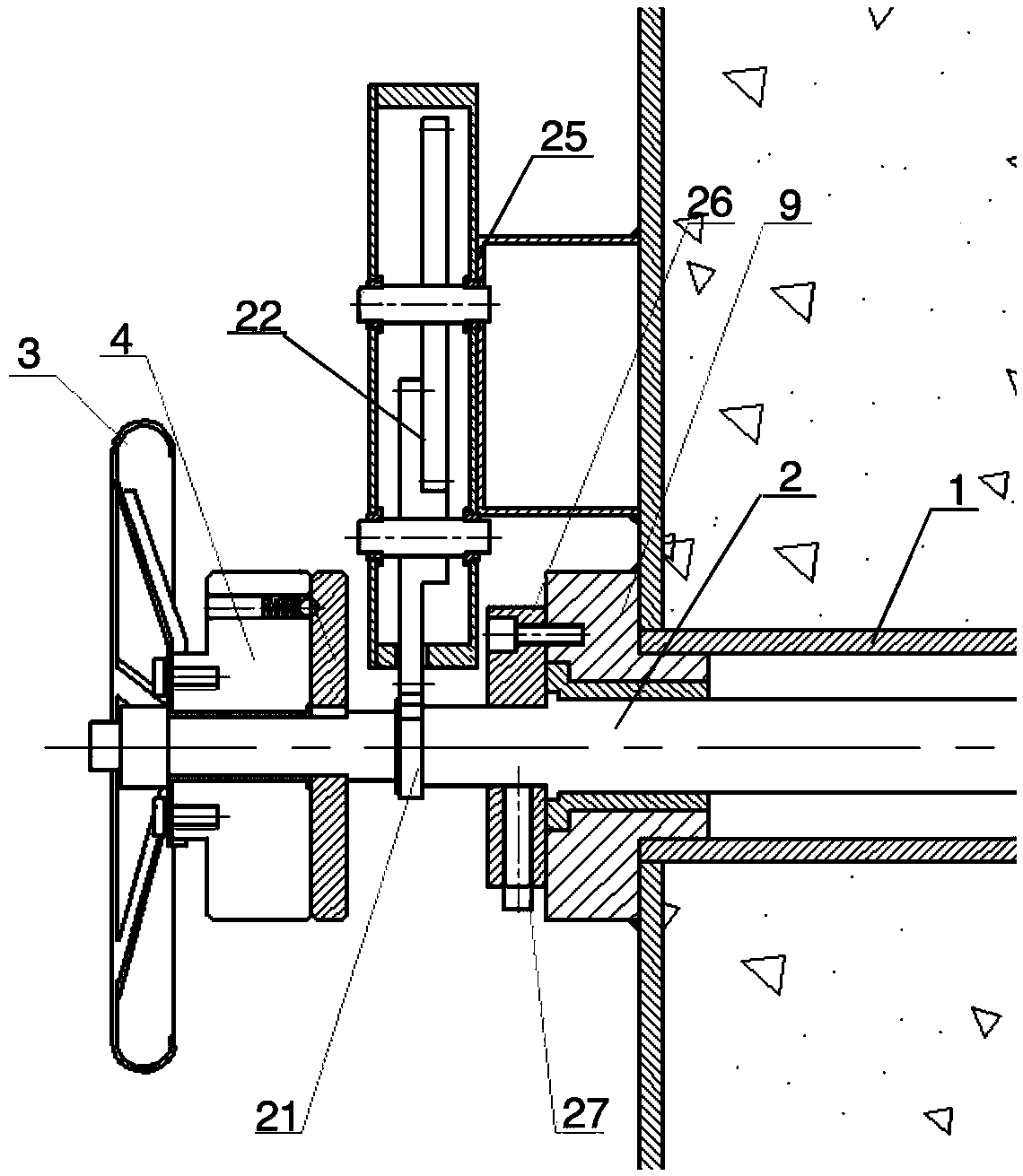
[0026] Such as Figure 1-3 Shown: This embodiment is an extension rod of an injection needle valve for an AP1000 reactor type nuclear power unit, including a sleeve 1, an extension rod shaft 2, a hand wheel 3, a de-force device 4, a connecting pipe 5, an adjustment rod 6 and a needle type Valve locking device 7, the sleeve 1 is fixed and installed in the wall, one end of the sleeve 1 is located indoors, the other end is located outdoors, and the end of the sleeve 1 located indoors is provided with an inner flange 8, and the end of the sleeve 1 located outdoors The end of the sleeve 1 is provided with an outer flange 9, the extension rod shaft 2 passes through the inside of the sleeve 1 and is connected to the sleeve 1 through the inner flange 8 and the outer flange 9 in rotation, and the hand wheel 3 is connected to the force-releasing device 4, The ...


PUM


Abstract

The invention discloses a jet needle valve extension rod for an AP1000 pile type nuclear power unit. The jet needle valve extension rod comprises a sleeve fixedly arranged in a wall in a penetrating manner, the end, located in a room, of the sleeve is provided with an inner flange, and the end, located outside the room, of the sleeve is provided with an outer flange; an extension rod shaft penetrates through the sleeve to be in rotating connection with the sleeve, a hand wheel is connected with a force stripping device, the force stripping device is connected to the end, located outside the room, of the extension rod shaft in a sleeved manner, and the end, located in the room, of the extension rod shaft is connected with a connection pipe; and one end of an adjustment rod is inserted into the connection pipe, the other end of the adjustment rod is connected with a needle valve locking device, the needle valve locking device is locked to a jet needle valve, and the extension rod shaft is rotated through the hand wheel and the force stripping device to drive the connection pipe and the adjustment rod to rotate to switch on or switch off the jet needle valve. By means of the jet needle valve extension rod, the situation that operators enter a radiating area to operate the jet needle valve is effectively avoided, radiation threats to the operators are avoided, and the physical and psychological health of the operators is effectively protected.

Description

technical field [0001] The invention relates to an extension rod, in particular to a jet needle valve extension rod for an AP1000 reactor type nuclear power unit, and belongs to the technical field of nuclear power unit equipment. Background technique [0002] The injection needle valve for AP1000 reactor nuclear power unit is installed in the area with heavy nuclear radiation, and the operating space is very tight. At the same time, due to the frequent operation of the injection needle valve, if the personnel directly operate it, the operator will be threatened by radiation. It will cause great danger to the health of the operators, which will inevitably affect the physical and mental health of the operators. Therefore, we are invited by the nuclear power plant to design a technical solution to this technical problem. Contents of the invention [0003] After the actual investigation on the site and the measurement of the specific current situation, the present invention p...

Claims


Application Information

Patent Timeline
Patent Type & Authority Patents(China)
IPC IPC(8): F16K37/00F16K31/46
CPCF16K31/46F16K37/0016
Inventor 王泽超吴桂章刘莉莉
Owner 江苏华洋新思路能源装备股份有限公司
Learn More