Solderable electric conductive gasket

a soldering gasket and soldering technology, applied in the field of soldering electric conductive gaskets, can solve the problems of electrically conductive material being easily separated from the support layer which is soldered, affecting the life of the device, noise, etc., and achieves the effect of easy separation or disassembly

Active Publication Date: 2021-11-30
JOINSET
View PDF11 Cites 0 Cited by
  • Summary
  • Abstract
  • Description
  • Claims
  • Application Information

AI Technical Summary

Benefits of technology

[0019]Another object of the present invention is to provide an electrically conductive solderable gasket in which repeatedly applied compressive force is not concentrated at a certain portion of a metal layer, thereby reducing breakage or damage at a local portion of the metal layer and increasing the operation length of the electrically conductive solderable gasket.
[0020]A further another object of the present invention is to provide an electrically conductive solderable gasket making it possible to stably perform a vacuum pick-up operation and a reflow soldering operation using a solder cream and guarantee sufficient soldering strength.
[0021]A still further another object of the present invention is to provide an electrically conductive solderable gasket configured to be easily manufactured and having a simple structure.
[0026]Beads may be formed to protrude from bent portions between the extensions and the first and second fitting portions so as to increase mechanical strength of the bent portions.

Problems solved by technology

In terms of electronic device design, various electromagnetic waves generated in circuits or the like may cause malfunctions of surrounding electronic devices and may thus result in performance degradation, noise, image distortion, a decrease in device lifespan, defective products, or the like.
In the related art, when the electrically conductive material is lifted by external force, the bent portion of the support layer does not sufficiently resist the lifting and thus unfolds or widens, and as a result, there is a drawback in that the electrically conductive material is easily separated from the support layer which is soldered.
In particular, when the length of the gasket is smaller than the width of the through-hole, the drawback is that the support layer is easily separated.
In addition, a portion of the support layer placed in parallel with a lower surface of the gasket is simply flat, and thus there is a drawback in that it is difficult to provide additional merits.
When the fixing portion provided in the hole is integrally formed in the gasket, the elastic body is not detached by external force after soldering, but in this case, there is a drawback in that it is difficult to uniformly insert the fixing portion having a relatively large length and an appropriate width while passing the fixing portion through the hole having a relatively small width.
In particular, since the electrode has to be narrower than the hole for ease of manufacturing, the width of the contact portions of the electrode is smaller than the width of the lower surface of the elastic body, thereby resulting in drawbacks such as low soldering strength and shaking or twisting during a reflow soldering process.
In addition, since the contact portions formed outside the hole are apart from each other, there is a drawback in that shaking or twisting occurs largely during a reflow soldering process.
In addition, if both ends of the fixing portion provided in the hole are separable, it is easy to fit the fixing portion, but in this case, drawbacks as in U.S. Pat. No. 7,129,421 arise.
However, when the electrical contact terminal is used in a vehicle which frequently wobbles and particularly the electrical contact terminal has a small length, the electrical contact terminal fixed to a circuit board by soldering a lower end portion of the metal layer of the electrical contact terminal to the circuit board using a solder cream is disadvantageous in that external compressive force repeatedly applied to the electrical contact terminal is hardly absorbed in a boundary between the soldered portion of the metal layer and the other non-soldered portion of the metal layer but is repeatedly concentrated in the boundary and may thus lead to the breakage of the metal layer.
For example, the soldered portion of the metal layer is not flexible because the soldered portion is combined with a solid solder as one part, and thus it is difficult to transmit external force applied to the soldered portion, thereby resulting in repeated concentration of force at the soldered portion and fracture of the soldered portion of the metal layer.
In addition, since the solder cream causes a lead rising phenomenon in the height direction of the metal layer, the electrical contact terminal has a drawback such as a small push operation length, which makes it difficult to provide a sufficient operation length in a product having a small height, and poor properties such as a poor repetitive-compression recovery rate.

Method used


Image

  • Solderable electric conductive gasket
  • Solderable electric conductive gasket
  • Solderable electric conductive gasket

Examples


Embodiment Construction

[0040]Technical terms used in the present invention are only for explaining specific embodiments while not limiting the present invention. In addition, unless otherwise defined, technical terms used in the present invention have the same meaning as commonly understood by those of ordinary skill in the art and will not be interpreted in an overly broad or narrow sense.

[0041]Hereinafter, specific embodiments of the present invention will be described in detail with reference to the accompanying drawings.

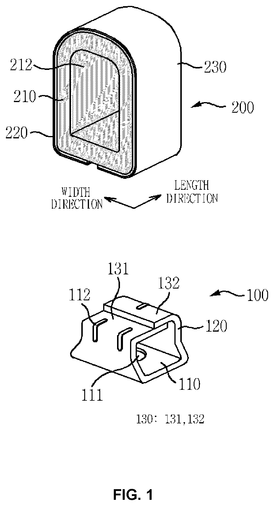
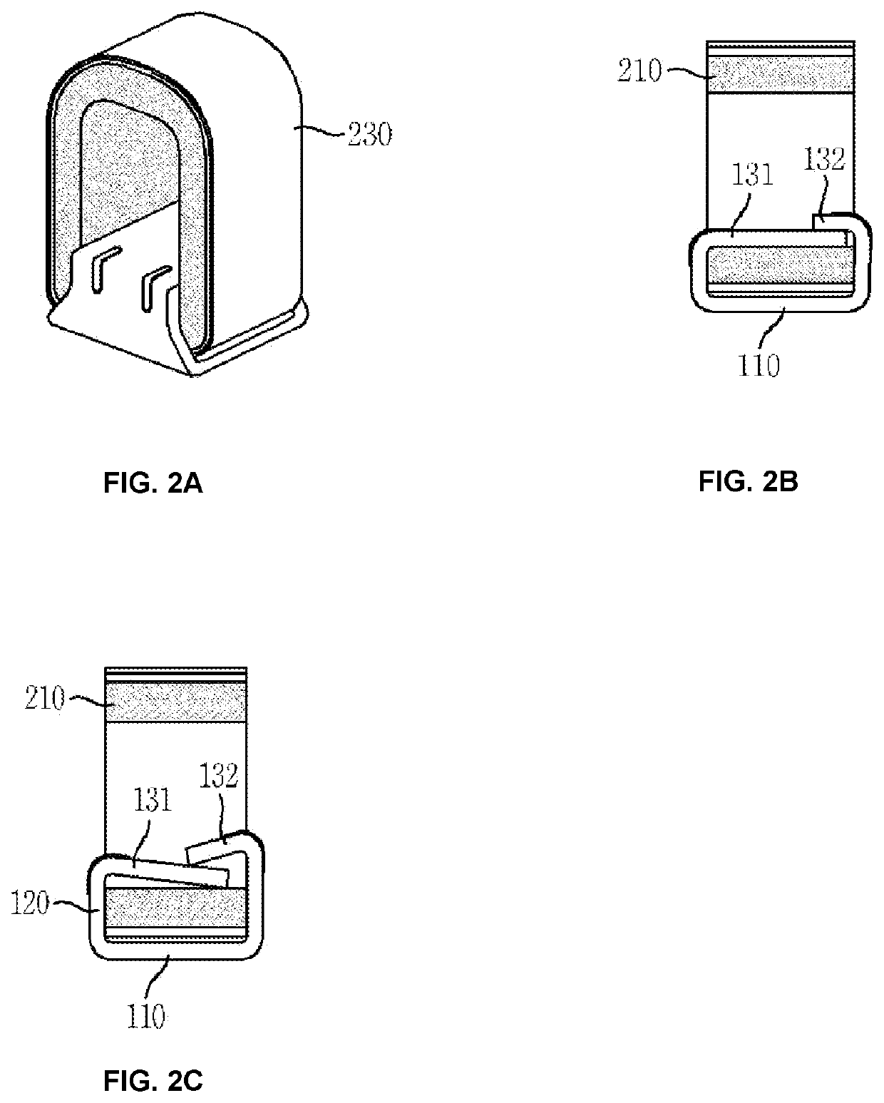
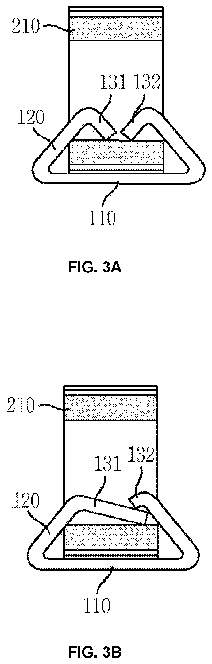
[0042]FIG. 1 is an exploded perspective view illustrating an electrically conductive solderable gasket according to an embodiment of the present invention, FIGS. 2A and 2B are an assembled perspective view and a vertical cross-sectional view which illustrate the electrically conductive solderable gasket, and FIG. 2C a vertical cross-sectional view illustrating the electrically conductive solderable gasket according to another example.

[0043]The electrically conductive solderable gasket ...


PUM

PropertyMeasurementUnit
thicknessaaaaaaaaaa
acute angleaaaaaaaaaa
electrically conductiveaaaaaaaaaa

Abstract

Provided is an electrically conductive solderable gasket configured to be not easily separated or detached from a circuit board by external force after the electrically conductive solderable gasket is mounted on the circuit board by soldering. The gasket includes: a single-body metallic support and an elastic electrical contact terminal which is superposed on an upper portion of the support and into which portions of the support are fitted, wherein the support includes a fixing portion, extensions bent upward from both lengthwise ends of the fixing portion, and first and second fitting portions bent inward respectively from upper ends of the extensions, wherein the first and second fitting portions are fitted into a through-hole of the electrical contact terminal and overlap each other in a state in which a lower surface of a metal layer of the electrical contact terminal is placed in contact with the fixing portion.

Description

REFERENCE TO RELATED APPLICATIONS[0001]This application claims the priority benefit of Korean Patent Application No. 10-2019-0069377 filed on Jun. 12, 2019 and Korean Patent Application No. 10-2020-0061880 filed on May 22, 2020, the entire contents of which are incorporated herein by reference.FIELD OF THE INVENTION[0002]The present invention relates to an electrically conductive solderable gasket, and particularly, to a technique for preventing an electrical contact terminal from being easily separated due to external force after an electrically conductive solderable gasket is mounted on a circuit board by soldering.[0003]In addition, the present invention relates to a technique for reducing the breakage or deformation of an electrical contact terminal caused by repeatedly applied compressive force.BACKGROUND OF THE INVENTION[0004]Electromagnetic waves generated in circuits of electronic devices or the like are radiated to the outside through air or are conducted through wires. In ...

Claims


Application Information

Patent Timeline
Patent Type & Authority Patents(United States)
IPC IPC(8): H05K9/00H05K3/34H05K3/30
CPCH05K9/0028H05K3/341H05K9/0015H05K9/0084H05K3/305H05K2201/10371H05K9/0016H05K13/0465H05K3/3494H05K3/3426Y02P70/50Y10S277/92
Inventor KIM, SUN-KIKANG, TAE-MANCHOKIM, GYU-SEOP
Owner JOINSET
Why Eureka
Try Eureka