Liquid crystal module and liquid crystal display device

A liquid crystal display device and liquid crystal module technology, which is applied in nonlinear optics, instruments, optics, etc., can solve the problems of product appearance restriction, low production efficiency, and large supply pressure of accessories, so as to save screw assembly or bonding The effect of reducing the adhesive bonding time, improving production efficiency and reducing supply pressure

Inactive Publication Date: 2017-09-29
HISENSE VISUAL TECH CO LTD
View PDF6 Cites 15 Cited by
  • Summary
  • Abstract
  • Description
  • Claims
  • Application Information

AI Technical Summary

Problems solved by technology

Using this screw connection method achieves a simple and beautiful appearance, but increases the thickness of the middle frame, which is not conducive to the frameless liquid crystal display device; and the production efficiency of the screw connection in the complete machine assembly plant in the prior art is relatively low. Low pressure, high pressure from spare parts supply, etc., product appearance is also subject to certain restrictions

Method used


Image

  • Liquid crystal module and liquid crystal display device
  • Liquid crystal module and liquid crystal display device
  • Liquid crystal module and liquid crystal display device

Examples


Embodiment 1

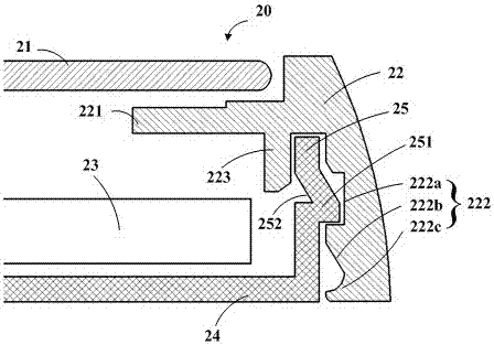
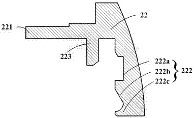
[0025] Embodiment 1 of the present application provides a liquid crystal module, such as Figure 2-Figure 6 shown. The liquid crystal module 20 includes a middle frame 22, a light guide plate 23, a back plate 24 and a first vertical plate 25, wherein the back plate 24 is located under the light guide plate 23, at the edge of the back plate 24 and toward the guide A first vertical plate 25 extends in the direction of the light plate 23; the middle frame includes a second vertical plate 222 and a third vertical plate 223 arranged on both sides of the first vertical plate 25, and the The first supporting part 221 that is vertically connected with the third vertical plate 223; the outer surface of the first vertical plate 25 includes a plurality of buckle protrusions 251 arranged at intervals, and the second vertical plate 222 is provided with the The buckle groove 222a matched with the buckle protrusion 251; the second vertical plate 222 also includes a detachment prevention gro...

Embodiment 2

[0036] Embodiment 2 of the present application further provides a liquid crystal display device, which includes a panel 21 and the liquid crystal module 20 described in Embodiment 1 above. Wherein, the liquid crystal module 20 and the panel 21 are in relative positions, and the panel 21 is located on the upper surface of the first supporting portion 221 of the liquid crystal module; the structure, function and function of the liquid crystal module 20 have been described in detail in the foregoing embodiments, and will not be described here. Let me repeat.


PUM


Abstract

The invention provides a backlight module and a liquid crystal display device. A liquid crystal module comprises a light panel, a backplane and a middle frame, wherein the backplane is located below the light panel, and a first vertical plate is located on the edge of the backplane and extends towards the light panel; the middle frame comprises a second vertical plate and a third vertical plate which are arranged on two sides of the first vertical plate and a first support portion which is vertically connected with the second vertical plate and the third vertical plate; a plurality of buckle protrusions which are arranged at intervals are arranged on the side face of the first vertical plate, and buckle grooves which are matched with the buckle protrusions are formed in the second vertical plate; the second vertical plate further comprises a drop proof groove which is located on the end portion and a guide arm which is connected with the buckle grooves and the drop proof groove. The liquid crystal display device comprises a panel and the liquid crystal module. According to the backlight module and the liquid crystal display device, fixation with no screw of a front frame and the backplane can be achieved, the work efficiency of a complete machine assembling factory is improved, and the product appearance is optimized.

Description

technical field [0001] The invention relates to the field of display technology, in particular to a liquid crystal module and a liquid crystal display device. Background technique [0002] The important components of the liquid crystal display device are the panel and the liquid crystal module. Based on the current demand for product appearance and aesthetics, the narrowing of the bezel width of the LCD TV has become a trend. The ultimate narrow bezel is actually a bezel-less design. In the prior art, the common frameless design of the liquid crystal module is mostly combined with the appearance part and the support part by screws or adhesives. The matching structure of the front shell of the liquid crystal module is as follows: figure 1 shown. [0003] Combine below figure 1 The structural diagram of illustrates the shortcomings of the prior art. The liquid crystal module 10 in the existing borderless liquid crystal display device mainly includes a middle frame 11 and a ...

Claims


Application Information

Patent Timeline
Patent Type & Authority Applications(China)
IPC IPC(8): G02F1/1333
CPCG02F1/133308G02F1/133317
Inventor 马骥陈雄
Owner HISENSE VISUAL TECH CO LTD
Why Eureka
Try Eureka