220kv Anti-icing and Anti-thunder composite insulator

A composite insulator, anti-icing technology, applied in insulators, suspension/strain insulators, electrical components, etc., can solve the problems of not considering the degree of icing, optimized design, small shed gap, etc., to achieve good flow performance and reasonable structure. , the effect of easy promotion and application

Inactive Publication Date: 2017-09-29
JIANGSU XIANGYUAN ELECTRIC EQUIP
View PDF0 Cites 4 Cited by
  • Summary
  • Abstract
  • Description
  • Claims
  • Application Information

AI Technical Summary

Problems solved by technology

[0002] The gap between the sheds of existing umbrella-shaped composite insulators is generally small, and it is easy to be bridged by ice edges, and its electrical performance drops significantly, even lower than that of porcelain and glass insulator strings at the same structural height.
In the current research on the umbrella structure, there is no separate optimization design for heavily iced lightning strike areas, and there is no optimization scheme that combines ice lightning and lightning lightning related theories. For example, none of the published patents consider the degree of ice coverage. Influenced and did not optimize the design of the umbrella structure from the perspective of the ice-covered flashover electric field and the discharge process; through a large-scale multifunctional artificial climate chamber, the charged icing and flashover characteristics tests of different umbrella-shaped composite insulators were carried out, and the research results It shows that under the condition of heavy ice (d>20mm), the ice edge of the shed will grow until it bridges the spacing of the sheds, even if the super large shed with a large spacing is no exception, and the diameter, number and interposition position of the sheds will all change. Significantly affects its Ice Flash properties

Method used


Image

  • 220kv Anti-icing and Anti-thunder composite insulator
  • 220kv Anti-icing and Anti-thunder composite insulator
  • 220kv Anti-icing and Anti-thunder composite insulator

Examples


Embodiment Construction

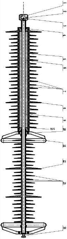
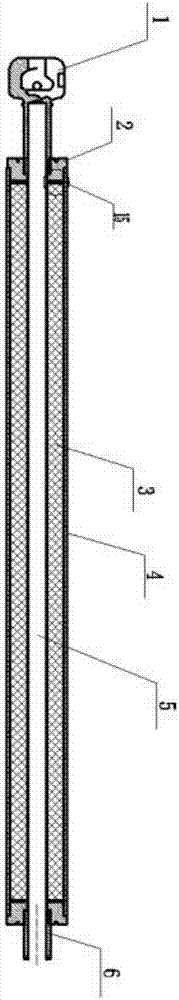
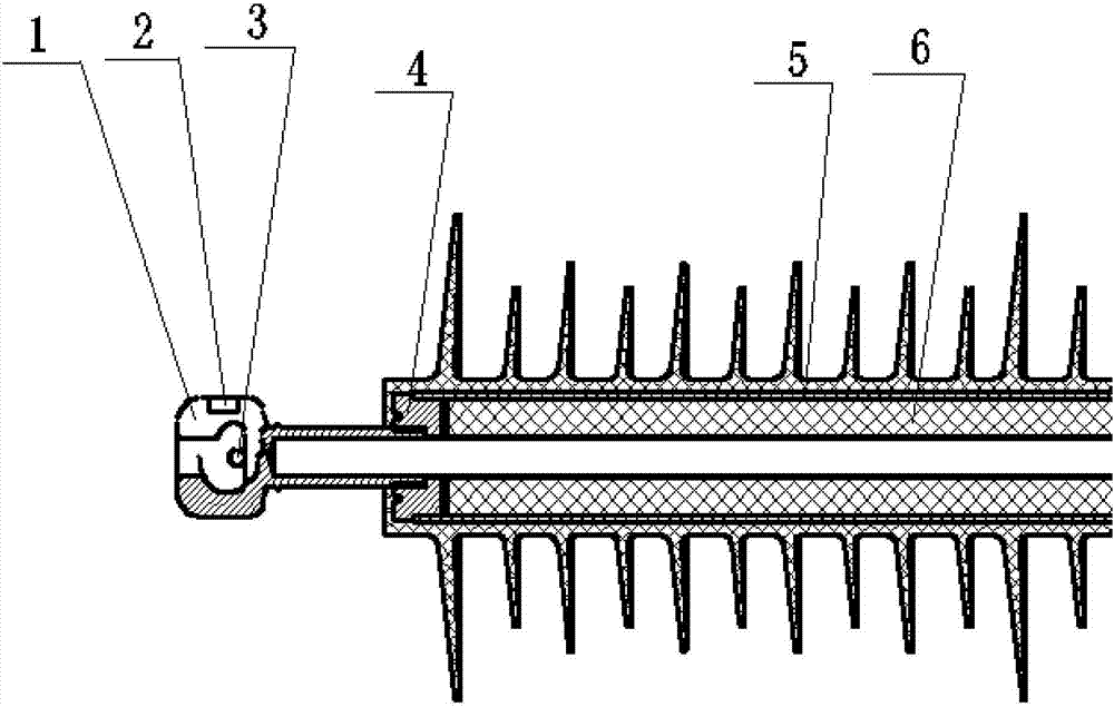
[0015] figure 1 , figure 2 , image 3 , Figure 4 It is a schematic diagram of the present invention; as shown in the figure: a 220kV ice and lightning protection composite insulator, characterized in that it includes a ball socket (1), a nameplate (2), a 20R type locking pin (3), and an electrode (4) , winding tube (5), zinc oxide resistor (6), upper umbrella (8), shed shed one (7), mandrel (9), connecting sleeve (10), equalizing ring (11), lower end The large umbrella (12), the second umbrella skirt cover (13), the ball head (14), the wave spring washer (15), the nameplate (2) is pasted on the ball socket (1), and the 20R type locking pin (3) is installed on the The inside of the ball socket (1) is used to lock the ball socket (1) and one end of the mandrel (9); the ball head (14) is installed on the other end of the mandrel (9), and the wave spring washer (15) Tightly installed on both ends of the zinc oxide resistance sheet (6); the upper end of the electrode (4) is i...


PUM

PropertyMeasurementUnit
diameteraaaaaaaaaa
diameteraaaaaaaaaa

Abstract

The invention discloses a 220kV anti-icing and lightning-proof composite insulator, the nameplate of which is pasted on the ball socket, the 20R type locking pin is installed inside the ball socket for locking the ball socket and one end of the mandrel, and the ball head is installed on the core On the other end of the rod, the zinc oxide resistor is set on the upper part of the mandrel, the wave spring washer is pressed and installed on the upper end of the zinc oxide resistor, the upper end of the electrode is installed on the wave spring washer, the lower end is installed on the lower end of the zinc oxide resistor, and the connecting sleeve is set on the core. In the middle of the rod, the winding tube, zinc oxide resistor, upper umbrella, lower umbrella, umbrella skirt 1, mandrel, pressure equalizing ring, and umbrella skirt 2 are all arranged outside the mandrel in an orderly manner, and the mechanical strength of the whole product is Beared by the middle mandrel, it is used in heavily ice-covered areas and common minefields. It has the advantages of reasonable structure, good electrode contact, and high mechanical strength of the product, and is easy to popularize and apply.

Description

technical field [0001] The invention belongs to the technical field of high voltage and insulation, in particular to a 220kV anti-icing and lightning-proof composite insulator. Background technique [0002] The gap between the sheds of the existing composite insulators with umbrella structures is generally small, and they are easily bridged by ice edges, and their electrical performance drops significantly, even lower than that of porcelain and glass insulator strings at the same structural height. In the current research on the umbrella structure, there is no separate optimization design for heavily iced lightning strike areas, and there is no optimization scheme that combines ice flash and lightning lightning related theories. For example, none of the published patents consider the degree of ice coverage. Influenced and did not optimize the design of the umbrella structure from the perspective of the ice-covered flashover electric field and the discharge process; through a...

Claims


Application Information

Patent Timeline
Patent Type & Authority Applications(China)
IPC IPC(8): H01B17/04H01B17/48H01B17/46H01B17/38
CPCH01B17/04H01B17/38H01B17/46H01B17/48
Inventor 刘铁桥张斌张达武纪福俊章玉秀朱勇飞王丹丹张德进
Owner JIANGSU XIANGYUAN ELECTRIC EQUIP
Why Eureka
Try Eureka