
A process method for non-inverted forming of bottom lead-out devices

A process method and device technology, which is applied in the field of safety and reliability of electronic components, can solve problems such as inability to meet inversion forming and short lead wires, and achieve the effects of improving environmental adaptability, good universality, and cost saving

Active Publication Date: 2019-07-23
郑州兴航科技有限公司
View PDF5 Cites 0 Cited by
  • Summary
  • Abstract
  • Description
  • Claims
  • Application Information

AI Technical Summary

Problems solved by technology

[0003] The common practice now is to invert the device by the operator according to the requirements, so that its leads form an inverted cantilever beam junction, such as figure 1 As shown, the leads from the bottom of the existing domestic QFP and SOP packaged devices are relatively short, which cannot meet the inversion forming specified in the standard, such as figure 2 As shown, if figure 2 In the later stage of the test, the stress of the lead solder joints cannot be released, resulting in solder joint problems. In order to avoid the release of the stress of the lead solder joints of the bottom lead QFP and SOP packaged devices in the later stage, the leads must be non-inverted.

Method used


Image

  • A process method for non-inverted forming of bottom lead-out devices
  • A process method for non-inverted forming of bottom lead-out devices
  • A process method for non-inverted forming of bottom lead-out devices

Examples


Embodiment Construction

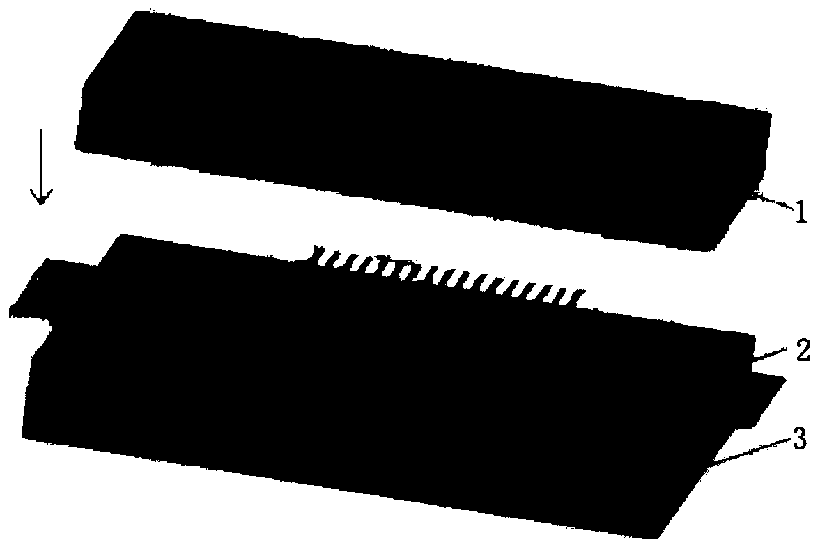
[0029] The invention discloses a process method for non-inverted forming of bottom-leading devices, which is different from the traditional inverting forming method, but adopts a non-inverting forming method that is compatible with the lead length of the original device, and is based on domestic bottom-leading QFP and SOP packaging devices. Particularity, that is: the way the device leads extend out is from the bottom, and the length of the device leads is relatively short. However, the above two characteristics cannot meet the requirements of QJ 3171 "Technical Requirements for Forming Components of Aerospace Electronic and Electrical Products", resulting in the failure of the device to be formed, and the solder joints may be affected by stress after welding in the later stage. Design a new forming method and a special forming tool for the implementation process, which can carry out non-inverted forming of domestic bottom-leading QFP and SOP packaged devices. After forming, th...


PUM


Abstract

The invention discloses a process method for non-inverted formation of a bottom lead-out device. Firstly the formed device is put in a lead flattening tool to flatten the device lead; then the device of which the lead is flattened is reversely fixed on a cutting edge, and first time formation of the device is performed by using formation equipment upper and lower moulds; and finally the device is fixed on the cutting edge in a non-inverted way, and second time formation of the device is performed by using the formation equipment upper and lower moulds. According to the process method for non-inverted formation of the bottom lead-out device, the formed device is put in the lead flattening tool to flatten the device lead, and then formation is completed through forward and backward processing so that formation of the domestic bottom lead QFP and SOP packaging device can be realized through combination of the specificity of the domestic bottom lead QFP and SOP packaging device according to the idea of the non-inverted formation method with cooperation of the designed lead flattening moulds and the special formation cutting edge.

Description

technical field [0001] The invention belongs to the technical field of safety and reliability of electronic components, and in particular relates to a non-inverted forming method for bottom lead-out devices. Background technique [0002] According to the requirements of Article 4.4 of the QJ 3171 "Technical Requirements for Forming Components of Aerospace Electronic and Electrical Products", QFP and SOP packaged devices need to be formed before their leads are soldered. Various environmental test requirements after the printed board. [0003] The common practice now is to invert the device by the operator according to the requirements, so that its leads form an inverted cantilever beam junction, such as figure 1 As shown, the leads from the bottom of the existing domestic QFP and SOP packaged devices are relatively short, which cannot meet the inversion forming specified in the standard, such as figure 2 As shown, if figure 2 In the later stage of the test, the stress o...

Claims


Application Information

Patent Timeline
Patent Type & Authority Patents(China)
IPC IPC(8): H01L23/498H01L23/49H01L21/56H01L21/48
Inventor 栗凡陈鹏
Owner 郑州兴航科技有限公司
Learn More