Cutting device for power cable stripping

A technology of power cable and cutting device, which is applied in the direction of cable installation device, cable installation, dismantling/armored cable equipment, etc., to prevent deviation of cutting position, improve stability, and improve portability

Active Publication Date: 2017-09-29
国网河南省电力公司新野县供电公司
View PDF6 Cites 2 Cited by
  • Summary
  • Abstract
  • Description
  • Claims
  • Application Information

AI Technical Summary

Problems solved by technology

[0006] In view of this, the purpose of the present invention is to address the deficiencies in the prior art and provide a power cable peeling and cutting device. The present invention realizes the cutting of the cable insulation and separates the cable conductor and the The cable insulation is

Method used


Image

  • Cutting device for power cable stripping
  • Cutting device for power cable stripping
  • Cutting device for power cable stripping

Examples


Example Embodiment

[0033] Example one

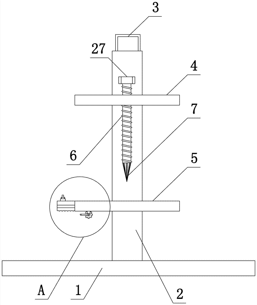
[0034] Such as Figure 1-4 As shown, the present invention includes a support base 1. The upper end of the support base 1 is fixedly connected to a support arm 2, the upper end of the support arm 2 is fixedly connected to a handle 3, and the support arm 2 is fixedly connected to an upper support plate 4 and a lower support plate 5 in the horizontal direction. , The upper support plate 4 is provided with a threaded hole in the vertical direction. The threaded hole is threaded to the first screw 6. The upper end of the first screw 6 is integrally formed with a hexagonal nut 27, and the lower end of the first screw 6 is welded with an insulation cutting knife 7, and the insulation The cutting knife 7 has a hexagonal pyramid structure, in which the edge of the hexagonal pyramid is a blade;
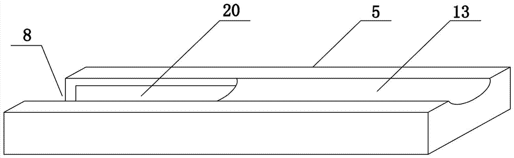
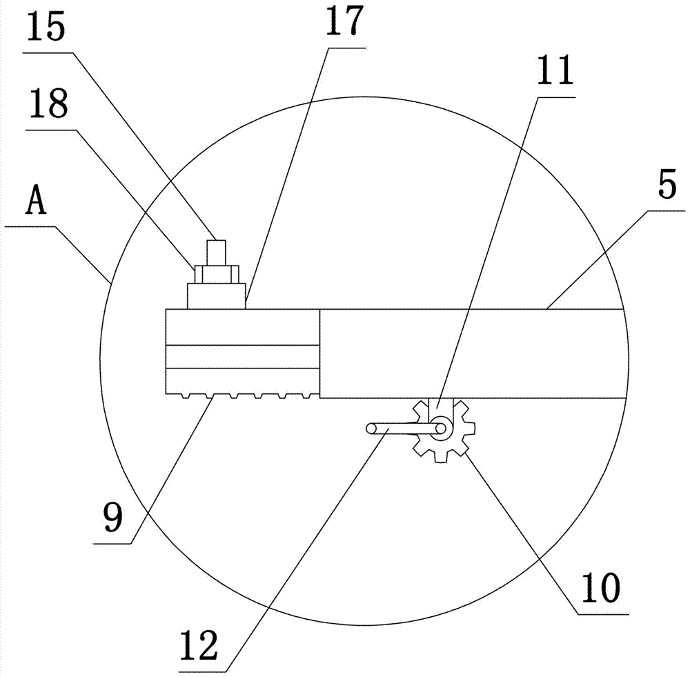
[0035] The left end of the lower support plate 5 is provided with an elongated slot 8 in which a straight rack 9 is slidably connected. A gear 10 is arranged below the straight...

Example Embodiment

[0036] Example two

[0037] Such as Figure 1-5 As shown, the present invention includes a support base 1, a support arm 2 is provided on the upper end of the support base 1, a handle 3 is provided on the upper end of the support arm 2, and the support arm 2 is provided with a horizontal upper support plate 4 and a lower support plate 5, and the upper support plate 4 Open a vertical threaded hole, the threaded hole is connected to the first screw 6, the upper end of the first screw 6 is integrally formed with a hexagonal nut 27, the lower end of the first screw 6 is provided with an insulating skin cutting knife 7, and the insulating skin cutting knife 7 is Hexagonal pyramid structure, in which the edge of the hexagonal pyramid is a knife edge;

[0038] An elongated slot 8 is provided at the left end of the lower support plate 5, and a straight rack 9 is slidably connected in the elongated groove 8. A gear 10 meshing with the straight rack 9 is arranged below the straight rack 9, ...

Example Embodiment

[0040] Example three

[0041] The structure of this embodiment is basically the same as that of the first embodiment, the difference is: Image 6 As shown, the upper end of the straight rack 9 is provided with a first wire groove 28, and the lower end of the wire pressing plate 16 is provided with a second wire groove 29. This structure effectively fits the outer wall of the cable wire by installing two wire grooves on the straight rack 9 The fixing prevents the cable conductor from being deformed during the clamping and fixing process of the conductor pressing plate 16 and the straight rack 9 to the cable conductor, especially when used on a steel strand cable, effectively preventing the problem of loose ends of the steel strand.


PUM


Abstract

The invention belongs to the technical field of power cables, and especially relates to a cutting device for power cable stripping. The cutting device comprises a support base. A support arm is arranged on the upper end face of the support base. The support base is equipped with an upper support plate and a lower support plate which are arranged horizontally. The upper support plate is equipped with an insulation cutter. The lower support plate is in sliding connection with a straight rack. A gear meshed with the straight rack is arranged below the straight rack. A handle is arranged at the axis of the gear. Second screws and third screws are arranged on the straight rack. The second screws are sleeved with a wire pressing plate. The third screws are sleeved with an insulation pressing plate. Positioning nuts are arranged at the upper ends of the second screws and the third screws. Through transmission fit between the gear and the straight rack, cable insulation can be cut, and a cable wire and cable insulation can be separated automatically for cable insulation stripping. The problem that personnel need to participate in operation is solved. Manual pull is not needed, and there is no need to strip a cable wire and cable insulation through secondary manual operation. Time and labor are saved, and the hands will not be hurt.

Description

technical field [0001] The invention belongs to the technical field of power cables, in particular to a peeling and cutting device for power cables. Background technique [0002] With the continuous development of the national economy and the strong advocacy of environmental protection, mechanical equipment using coal and petroleum as raw materials is gradually being replaced by electrical equipment, such as electric boilers, electric vehicles, etc. The changes in the structure of such products are invisible. The rapid increase in the demand for electricity caused by electricity, so electric power-related companies have developed a variety of high-load, high-power transmission equipment to meet the needs of the current situation. Among them, the promotion and use of overhead transmission lines with insulated cables has effectively avoided the failure of ordinary transmission lines Many problems, such as large energy loss, have improved the reliability of power supply, but in...

Claims


Application Information

Patent Timeline
IPC IPC(8): H02G1/12
CPCH02G1/126
Inventor 赵颖博翟建军陈静李勇李瑞
Owner 国网河南省电力公司新野县供电公司
Why Eureka
Try Eureka