Full adder based on FinFET device

A full adder and device technology, applied in the field of full adder based on FinFET devices, can solve the problems of long path, large delay, high height, etc.

Inactive Publication Date: 2017-09-29
NINGBO UNIV
View PDF3 Cites 0 Cited by
  • Summary
  • Abstract
  • Description
  • Claims
  • Application Information

AI Technical Summary

Problems solved by technology

The number of FINFET tubes used in the full adder is relatively large, resulting in large circuit area and power consumption; and the pull-down network stack composed of N-type FINFET tubes N1, N2, N3, N4, N5 and N6 has a high height, The pull-up path composed of P-type FINFET tubes P4, P5, P6, P7, P8, P9, P10, and P11 has a long path and a large delay, which is not conducive to fast evaluation

Method used


Image

  • Full adder based on FinFET device
  • Full adder based on FinFET device
  • Full adder based on FinFET device

Examples


Embodiment 1

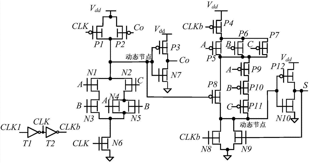
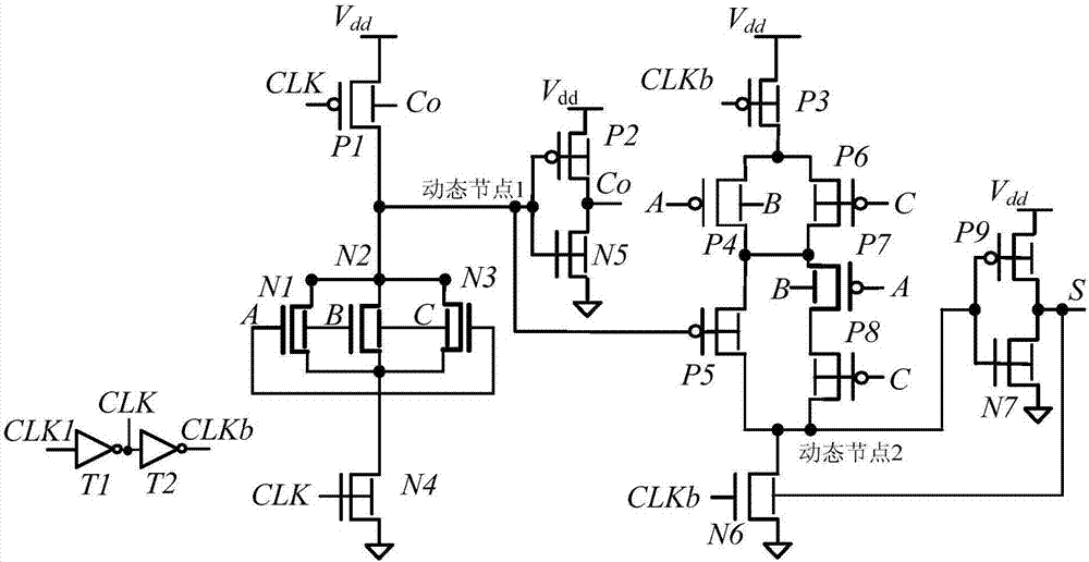
[0019] Embodiment one: if figure 2 As shown, a full adder based on FinFET devices includes a first N-type FinFET tube N1, a second N-type FinFET tube N2, a third N-type FinFET tube N3, a fourth N-type FinFET tube N4, and a fifth N-type FinFET tube N4. FinFET tube N5, sixth N-type FinFET tube N6, seventh N-type FinFET tube N7, first P-type FinFET tube P1, second P-type FinFET tube P2, third P-type FinFET tube P3, fourth P-type FinFET tube P4, the fifth P-type FinFET tube P5, the sixth P-type FinFET tube P6, the seventh P-type FinFET tube P7, the eighth P-type FinFET tube P8, the ninth P-type FinFET tube P9, the first inverter T1 and the The second inverter T2, the first N-type FinFET N1, the second N-type FinFET N2 and the third N-type FinFET N3 are all high-threshold N-type FinFETs, and the seventh P-type FinFET P7 is a high-threshold P-type FinFET tubes, the fourth N-type FinFET tube N4, the fifth N-type FinFET tube N5, the sixth N-type FinFET tube N6 and the seventh N-type...

Embodiment 2

[0020] Embodiment two: if figure 2As shown, a full adder based on FinFET devices includes a first N-type FinFET tube N1, a second N-type FinFET tube N2, a third N-type FinFET tube N3, a fourth N-type FinFET tube N4, and a fifth N-type FinFET tube N4. FinFET tube N5, sixth N-type FinFET tube N6, seventh N-type FinFET tube N7, first P-type FinFET tube P1, second P-type FinFET tube P2, third P-type FinFET tube P3, fourth P-type FinFET tube P4, the fifth P-type FinFET tube P5, the sixth P-type FinFET tube P6, the seventh P-type FinFET tube P7, the eighth P-type FinFET tube P8, the ninth P-type FinFET tube P9, the first inverter T1 and the The second inverter T2, the first N-type FinFET N1, the second N-type FinFET N2 and the third N-type FinFET N3 are all high-threshold N-type FinFETs, and the seventh P-type FinFET P7 is a high-threshold P-type FinFET tubes, the fourth N-type FinFET tube N4, the fifth N-type FinFET tube N5, the sixth N-type FinFET tube N6 and the seventh N-type ...

Embodiment 3

[0022] Embodiment three: as figure 2As shown, a full adder based on FinFET devices includes a first N-type FinFET tube N1, a second N-type FinFET tube N2, a third N-type FinFET tube N3, a fourth N-type FinFET tube N4, and a fifth N-type FinFET tube N4. FinFET tube N5, sixth N-type FinFET tube N6, seventh N-type FinFET tube N7, first P-type FinFET tube P1, second P-type FinFET tube P2, third P-type FinFET tube P3, fourth P-type FinFET tube P4, the fifth P-type FinFET tube P5, the sixth P-type FinFET tube P6, the seventh P-type FinFET tube P7, the eighth P-type FinFET tube P8, the ninth P-type FinFET tube P9, the first inverter T1 and the The second inverter T2, the first N-type FinFET N1, the second N-type FinFET N2 and the third N-type FinFET N3 are all high-threshold N-type FinFETs, and the seventh P-type FinFET P7 is a high-threshold P-type FinFET tubes, the fourth N-type FinFET tube N4, the fifth N-type FinFET tube N5, the sixth N-type FinFET tube N6 and the seventh N-typ...


PUM


Abstract

The invention discloses a full adder based on a FinFET device. The full adder comprises a first N type FinFET tube, a second N type FinFET tube, a third N type FinFET tube, a fourth N type FinFET tube, a fifth N type FinFET tube, a sixth N type FinFET tube, a seventh N type FinFET tube, a first P type FinFET tube, a second P type FinFET tube, a third P type FinFET tube, a fourth P type FinFET tube, a fifth P type FinFET tube, a sixth P type FinFET tube, a seventh P type FinFET tube, an eighth P type FinFET tube, a ninth P type FinFET tube, a first inverter and a second inverter. The full adder has the advantages that the circuit area, the delay, the power consumption and the power delay product are smaller without affecting the circuit performance.

Description

technical field [0001] The invention relates to a full adder, in particular to a full adder based on a FinFET device. Background technique [0002] As the process size enters the nanometer level, power consumption has become a problem that IC designers have to pay attention to. The full adder is the basic unit of all arithmetic circuits and one of the most critical components of the digital system. The power consumption and operation speed of the full adder directly determine the overall performance of the entire circuit system. Zipper CMOS full adder, as a representative of dynamic full adder, is widely used in the pipeline structure and critical path of microprocessors due to its fast speed and small area at the 90nm technology node. It is the multiplication and accumulation unit in the processor essential component. However, with the rapid development of CMOS integrated circuit technology, the device size is continuously reduced, and the clock frequency of the micropro...

Claims


Application Information

Patent Timeline
IPC IPC(8): H03K19/20G06F7/501
CPCH03K19/20G06F7/501
Inventor 胡建平杨会山杨廷锋
Owner NINGBO UNIV
Why Eureka
Try Eureka