
Method and system applicable to matching real address with network address of electronic equipment

A technology for electronic equipment and network addresses, applied in transmission systems, electrical components, etc., can solve problems such as the inability to obtain the coordinates of electronic equipment, the inability to obtain the network address of electronic equipment, and the acquisition of electronic equipment

Inactive Publication Date: 2017-09-29
林政宗
View PDF5 Cites 0 Cited by
  • Summary
  • Abstract
  • Description
  • Claims
  • Application Information

AI Technical Summary

Problems solved by technology

[0002] Existing computer systems cannot perform real-time matching between real addresses and their corresponding network addresses (including MAC addresses and IP addresses such as Ipv4 and Ipv6 addresses), that is, known address information (such as coordinates) in the real world. The computer system cannot obtain the network address of the electronic device at the address in real time only based on the address information
For example, if a coordinate information and altitude information are provided, the existing computer system cannot judge whether there is an electronic device at the spatial location based on this information, and if so, cannot obtain the network address of the electronic device
[0003] Or, if a network address (such as MAC address or IP address) is known, the existing computer system cannot obtain the actual address of the electronic device using the network address in real time only based on the network address
For example, if an IP address is provided, the existing computer system cannot determine whether there is an electronic device using the IP address (because not all electronic devices connected to the network respond to network requests, so it cannot be judged), and if so, it cannot be obtained to use the IP address. Address the coordinates of the electronic device

Method used


Image

  • Method and system applicable to matching real address with network address of electronic equipment
  • Method and system applicable to matching real address with network address of electronic equipment
  • Method and system applicable to matching real address with network address of electronic equipment

Examples


no. 1 example

[0060] This embodiment is the first working mode. In this working mode, the server stores the following corresponding information items for each electronic device, (coordinates, IP, MAC, timestamp, time threshold), where the coordinates are the The current coordinates of the electronic device can be two-dimensional coordinates or multi-dimensional coordinates; IP is the latest IP address of the electronic device; MAC is the MAC address of the electronic device; timestamp is the time when the electronic device saves the current state (ie the current entry The time of the last update); the time threshold is an estimated value of the stable time of the current state of the electronic device (that is, an estimated value of the stable time of the current entry). In the present invention, the expression (A, B) of an item means that the item includes at least A and B, the item (A, B, C) means that the item includes at least A, B, and C, and so on. There are various update models for ...

no. 2 example

[0087] This embodiment is the second working mode. In this working mode, the server stores the following corresponding information items for each electronic device, (coordinates, MAC, timestamp, time threshold), where the coordinates are the electronic device The current coordinates of , which can be two-dimensional coordinates or multi-dimensional coordinates; MAC is the MAC address of the electronic device; timestamp is the time when the electronic device saves the current state (that is, the time when the current entry is last updated); the time threshold is the electronic An estimate of the stable time for the current state of the device (ie, an estimate of the stable time for the current entry).

[0088] In this working mode, the workflow of the whole system is as follows:

[0089] client

[0090] The following operations can be performed using the client:

[0091] (1) Input the coordinates and query the IP address;

[0092] (2) Input the coordinates and query the MA...

no. 3 example

[0114] The present embodiment optimizes the system of the first working mode, and the workflow of the optimization system under the first working mode is as follows:

[0115] client

[0116] The following operations can be performed using the client:

[0117] (1) Input the coordinates and query the IP address;

[0118] (2) Input the coordinates and query the MAC address;

[0119] (3) Enter the IP address and query the coordinates;

[0120] (4) Enter the MAC address and query the coordinates.

[0121] Electronic equipment

[0122] The workflow of the electronic device is as follows:

[0123] (1) Initialize, save its current state (coordinates, IP, MAC, timestamp, category), and send the current state to the server, where the coordinates are the current coordinates of the electronic device, IP is the current IP address of the electronic device, and MAC is the electronic device The current MAC address, the timestamp is the time when the electronic device saves the curre...


PUM


Abstract

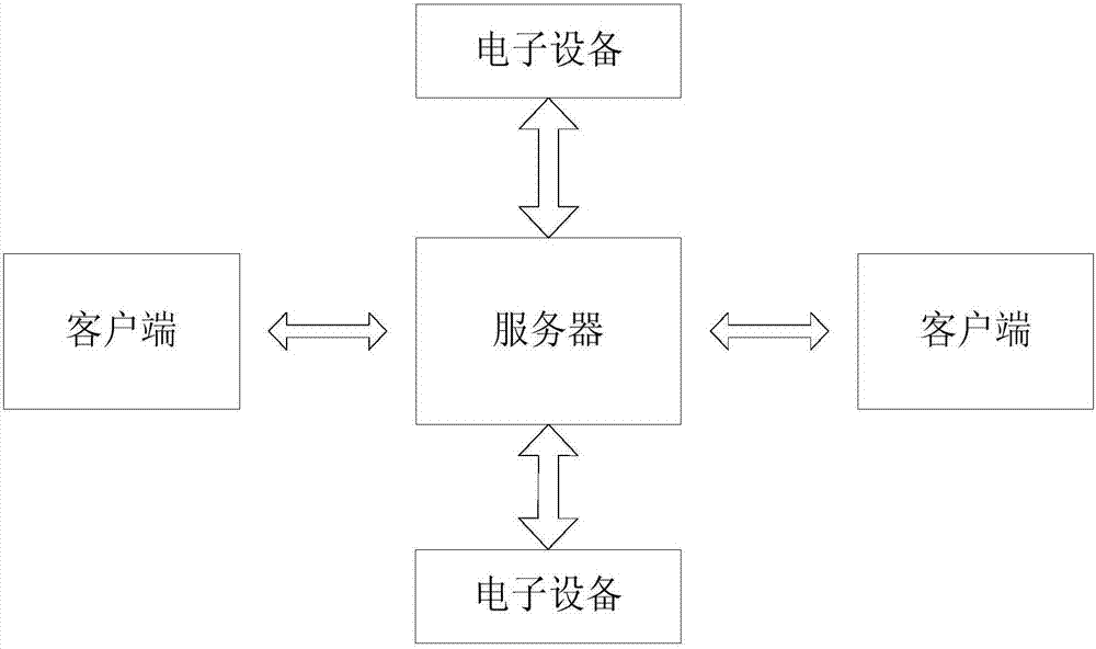
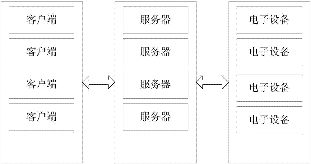
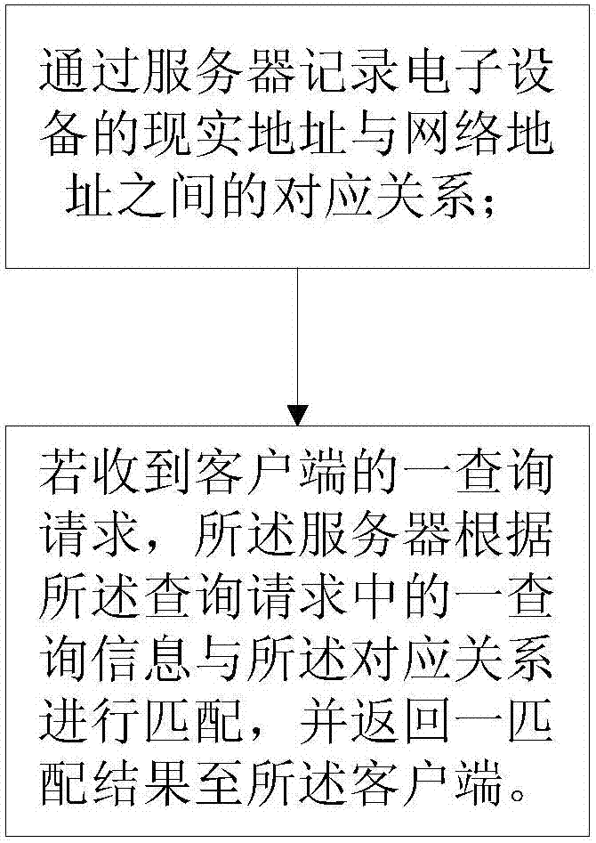
The invention discloses a method and a system applicable to matching a real address with a network address of electronic equipment. The method comprises the steps as follows: correspondence between the real address and the network address of the electronic equipment is recorded by a server; and if a query request from a client is received, the server performs matching according to query information in the query request and the correspondence, and returns a matching result to the client. According to the method and the system provided by the invention, mutual matching between the real address and the network address can be achieved.

Description

technical field [0001] The invention provides a method and system suitable for matching the actual address and network address of electronic equipment. Background technique [0002] Existing computer systems cannot perform real-time matching between real addresses and their corresponding network addresses (including MAC addresses and IP addresses such as Ipv4 and Ipv6 addresses), that is, known address information (such as coordinates) in the real world. The computer system cannot obtain the network address of the electronic device at the address in real time only based on the address information. For example, if coordinate information and altitude information are provided, the existing computer system cannot judge whether there is an electronic device at the spatial location based on this information, and if so, cannot obtain the network address of the electronic device. [0003] Or, a known network address (such as MAC address or IP address), the existing computer system ...

Claims


Application Information

Patent Timeline
Patent Type & Authority Applications(China)
IPC IPC(8): H04L29/12
CPCH04L61/25H04L2101/69
Inventor 林政宗
Owner 林政宗
Learn More