Dust hood device of torch cutting machine for continuous casting

A technology of dust removal hood and fire cutting machine is applied in the direction of removing smoke and dust, gas flame welding equipment, cleaning methods and utensils.

Pending Publication Date: 2017-10-03
HUATIAN ENG & TECH CORP MCC
View PDF16 Cites 6 Cited by
  • Summary
  • Abstract
  • Description
  • Claims
  • Application Information

AI Technical Summary

Problems solved by technology

In the continuous casting process workshop, there are few equipments that generate smoke and dust, mainly water vapor evaporated at high temperature, which has little impact on the environment. However, after the continuous casting billet comes out, it needs to be flame-cut accordi

Method used


Image

  • Dust hood device of torch cutting machine for continuous casting
  • Dust hood device of torch cutting machine for continuous casting
  • Dust hood device of torch cutting machine for continuous casting

Examples


Embodiment 1

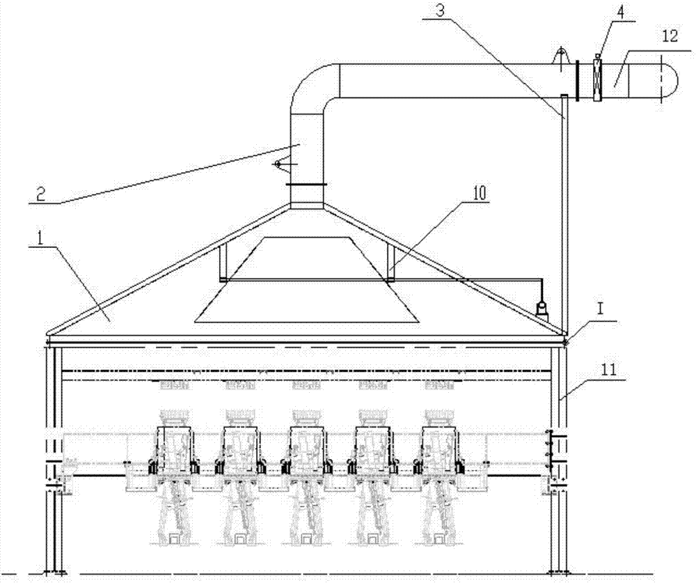
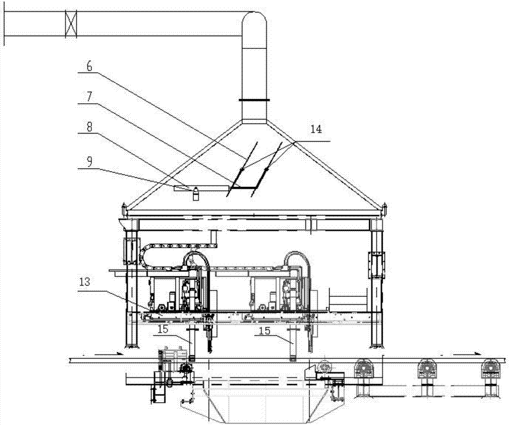
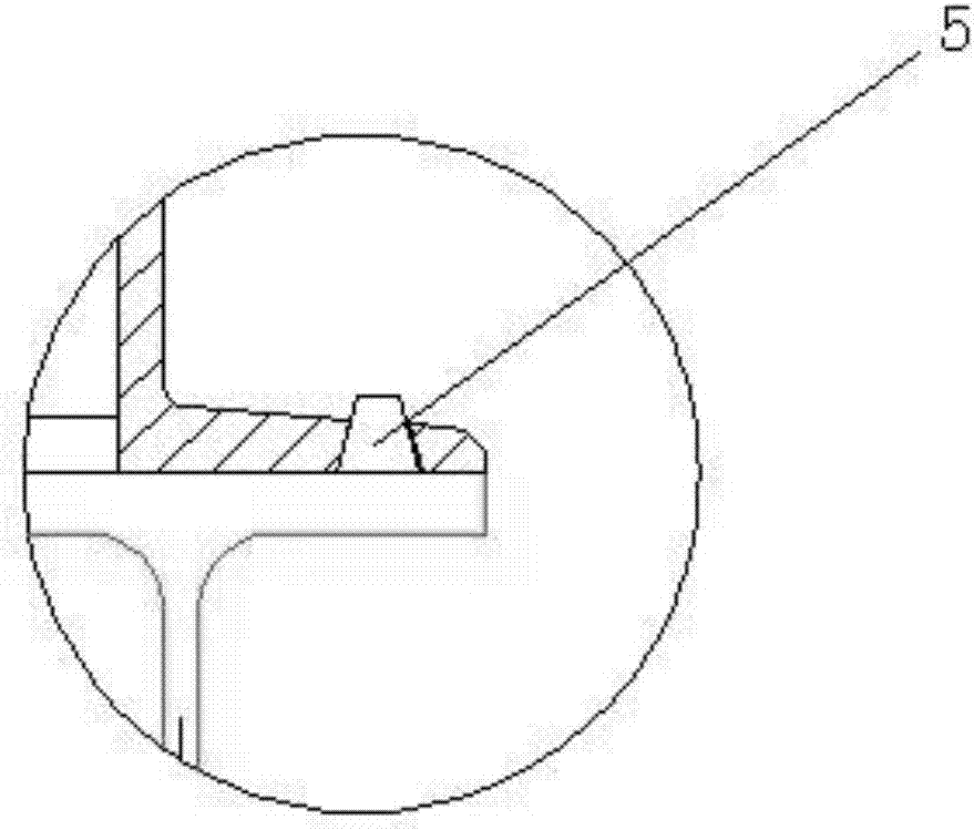
[0019] Such as Figure 1-Figure 4 As shown, the present invention is a dust removal hood device for a continuous casting torch cutter, which includes a dust removal hood 1, a dust removal pipe 2, a pipe support 3, an electric valve 4, a taper pin 5, an airflow guide device, a driving device 8 and a fixed base 9 .

[0020] The dust removal cover 1 is installed above the torch cutter support 11 by the taper pin 5 . The front end of the dust removal pipe 2 is connected to the dust removal cover body 1 through bolts. An electric valve 4 is installed at the end of the dust removal pipe 2. The electric valve 4 is connected to the main dust removal pipe 12 of the workshop. The electric valve 4 is used to close and adjust the dust removal air volume. The valve opening is controlled by hand. Manipulator control and digital display, and interlock with the main dust removal system. The bottom of the pipe support 3 is connected with the dust removal cover body 1, and the top is connecte...

Embodiment 2

[0024] In actual use, the working state of the invention of a continuous casting torch cutter dust removal cover device is as follows:

[0025] The device is installed on the fire cutter support 11, positioned and fixed by the taper pin 5, the action of the driving device 8 is interlocked and synchronized with the cutting action of the fire cutter 13, and the rod end of the driving device 8 is in a retracted state before working.

[0026] First, the electric valve 4 is opened, the dust removal cover 1 is connected to the main dust removal pipeline 12 of the workshop, and the dust removal work starts. Operate the hand operator to adjust the opening value of the electric valve 4 according to the actual situation. When the continuous casting slab reaches the cutting starting point 15 on the left side of the fire cutter 13, the cutting work of the fire cutter 13 starts, and at this time, the electric servo cylinder 8 starts to work synchronously. As the fire cutter 13 moves, the ro...


PUM


Abstract

The invention discloses a dust hood device of a torch cutting machine for continuous casting. The dust hood device of the torch cutting machine for continuous casting comprises a dust hood body, a dust collection pipe, a pipe support, an electric valve, an air flow guiding device, a driving device and a fixed base. The dust hood body is mounted above a torch cutting machine support through taper pins; the front end of the dust collection pipe is connected with the dust hood body through a bolt; the electric valve is mounted at the tail end of the dust collection pipe and is connected with a main dust collection pipe of a workshop; the air flow guiding device is further arranged in the dust hood body and is connected with a rod end of the driving device through a connecting rod mechanism; and the driving device is arranged on the outside of the dust hood body through the fixed base. During working of the device, the rod end of the driving device extends and drives the connecting rod mechanism to move counterclockwise, flow guiding plates rotate around a rotating center counterclockwise, on the contrary, the rod end of the driving device extends and drives the connecting rod mechanism to move clockwise, the flow guiding plates rotate around the rotating center clockwise, meanwhile, action of the driving device is interlocked with cutting action of the torch cutting machine, and soot of the torch cutting machine can be discharged effectively.

Description

technical field [0001] The invention relates to the continuous casting industry, in particular to a dust removal cover device for a continuous casting torch cutter. Background technique [0002] With the continuous improvement of environmental protection requirements, metallurgical environmental protection requirements also increase. Once the workshop environmental protection does not meet the standards, it must be closed for rectification. Therefore, any equipment that generates a large amount of smoke and dust must use a matching environmental protection dust removal device. In the continuous casting process workshop, there are few equipments that generate smoke and dust, mainly water vapor evaporated at high temperature, which has little impact on the environment. However, after the continuous casting billet comes out, it needs to be flame-cut according to the specified length, and a certain amount of smoke and dust will be generated when the billet is cut. Under the act...

Claims


Application Information

Patent Timeline
IPC IPC(8): B08B15/00B23K7/10
CPCB08B15/007B23K7/10
Inventor 查勇方强国徐云辉傅飞
Owner HUATIAN ENG & TECH CORP MCC
Why Eureka
Try Eureka