Digital hydraulic draught fan transmission system

A transmission system, digital technology, applied in the direction of transmission, wind turbine, machine/engine, etc., can solve the problems of high cost, many variable components, complex system control and optimization, etc., to achieve the effect of improving efficiency and reducing system cost

Pending Publication Date: 2017-10-03
ZHEJIANG UNIV
View PDF7 Cites 2 Cited by
  • Summary
  • Abstract
  • Description
  • Claims
  • Application Information

AI Technical Summary

Problems solved by technology

Although the parallel connection of multiple variable variable hydraulic motors can meet the requirements of high-power fans, there are many variable components, the system control and optimization are complicated, and the cost is high

Method used


Image

  • Digital hydraulic draught fan transmission system
  • Digital hydraulic draught fan transmission system
  • Digital hydraulic draught fan transmission system

Examples


Embodiment Construction

[0024] The present invention will be further described in detail below in conjunction with the drawings and specific embodiments.

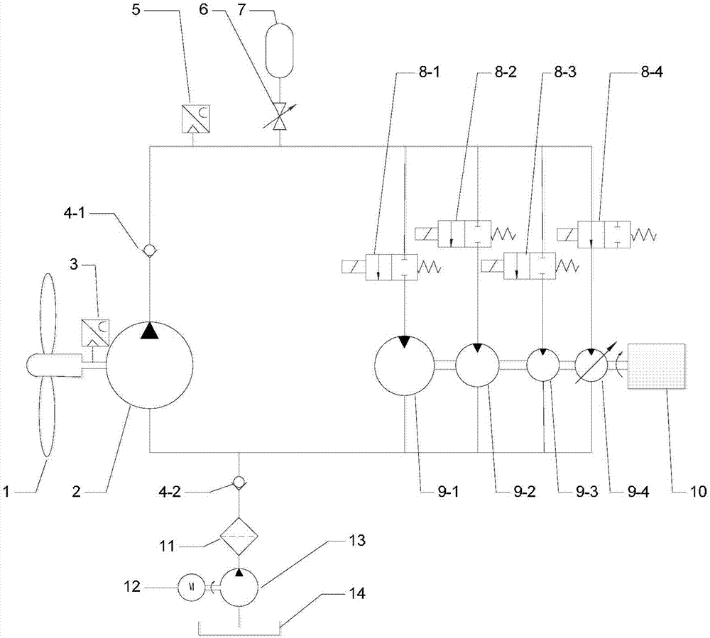
[0025] Such as figure 1 As shown, the digital hydraulic fan drive system implemented in the present invention mainly includes a fan 1, a first quantitative hydraulic pump 2, a speed sensor 3, a pressure sensor 5, a first reversing valve 8-1, and a second reversing valve 8. -2, the third reversing valve 8-3, the fourth reversing valve 8-4, the first quantitative hydraulic motor 9-1, the second quantitative hydraulic motor 9-2, the third quantitative hydraulic motor 9-3, variable Hydraulic motor 9-4, generator 10. The mechanical energy obtained by the fan 1 is transferred to the first quantitative hydraulic pump 2 and converted into hydraulic energy. The first quantitative hydraulic motor 9-1, the second quantitative hydraulic motor 9-2, the third quantitative hydraulic motor 9-3, and the variable hydraulic motor 9-4 converts hydraulic energy into mec...


PUM


Abstract

The invention discloses a digital hydraulic draught fan transmission system. A draught fan is connected with a first quantitative hydraulic pump, the first quantitative hydraulic pump is connected with a power generator through a hydraulic motor combination, wherein the hydraulic motor combination is formed by connecting a plurality of quantitative hydraulic motors and a variable hydraulic motor in parallel in a digital coding manner; the hydraulic motor combination is connected to the two ends of the first quantitative hydraulic pump in parallel; and the first quantitative hydraulic pump is connected with the hydraulic input end of the hydraulic motor combination through a one-way valve, an energy accumulator is connected between a first one-way valve and the hydraulic motor combination through a stop valve, and an oil tank is connected to the first hydraulic motor combination and the first quantitative hydraulic pump through a second quantitative hydraulic pump, a filter and a second one-way valve. Any displacement from zero to the maximum displacement is achieved through the hydraulic motor combination, influences of low displacement on the efficiency of the variable hydraulic motor are lowered to the minimum while the stepless speed regulating function is achieved, the efficiency of the transmission system at a low wind speed is improved, and meanwhile the system cost is also greatly lowered.

Description

Technical field [0001] The invention relates to a hydraulic fan drive system, in particular to a digital hydraulic fan drive system. Background technique [0002] In the prior art, wind turbines usually adopt gear transmission. In order to maximize the capture of wind energy, the speed of the fan blades needs to change with the wind speed. Since the gear transmission ratio is fixed, the generator speed also changes with the wind speed. In order to connect the generator to the grid, a power conversion device is needed to convert the frequency and voltage of the generator into the frequency and voltage required by the grid. The continuous change of wind speed will produce impact load on the fan blade shaft, and the rigid gear transmission cannot absorb the impact load on the shaft caused by the continuous change of wind speed, which causes the failure of the fan gear transmission. This further reduces the reliability of the fan system and increases the maintenance cost of the fa...

Claims


Application Information

Patent Timeline
IPC IPC(8): F03D15/10F16H39/02
CPCF16H39/02Y02E10/72
Inventor 王峰陈金成迈克尔·古斯特金·施特尔森
Owner ZHEJIANG UNIV
Why Eureka
Try Eureka