Heat exchange structure of reactor evaporator

A technology of heat exchange structure and evaporator, which is applied in steam generation, components of steam boilers, steam boilers, etc. It can solve the problems of poor vibration reduction efficiency of anti-vibration strips, achieve good lateral stability and reduce lateral vibration frequency and amplitude, the effect of improving stability

Active Publication Date: 2017-10-03
ANHUI KECHUANG INTELLIGENT INTPROP SERVICE CO LTD
View PDF4 Cites 2 Cited by
  • Summary
  • Abstract
  • Description
  • Claims
  • Application Information

AI Technical Summary

Problems solved by technology

[0003] The purpose of the present invention is to provide a heat exchange structure of a reactor evaporator to solve the problem of poor vibration damping efficiency of using anti-vibration strips in the prior art, and achieve the purpose of improving vibration damping efficiency and prolonging service life

Method used


Image

  • Heat exchange structure of reactor evaporator
  • Heat exchange structure of reactor evaporator

Examples


Embodiment 1

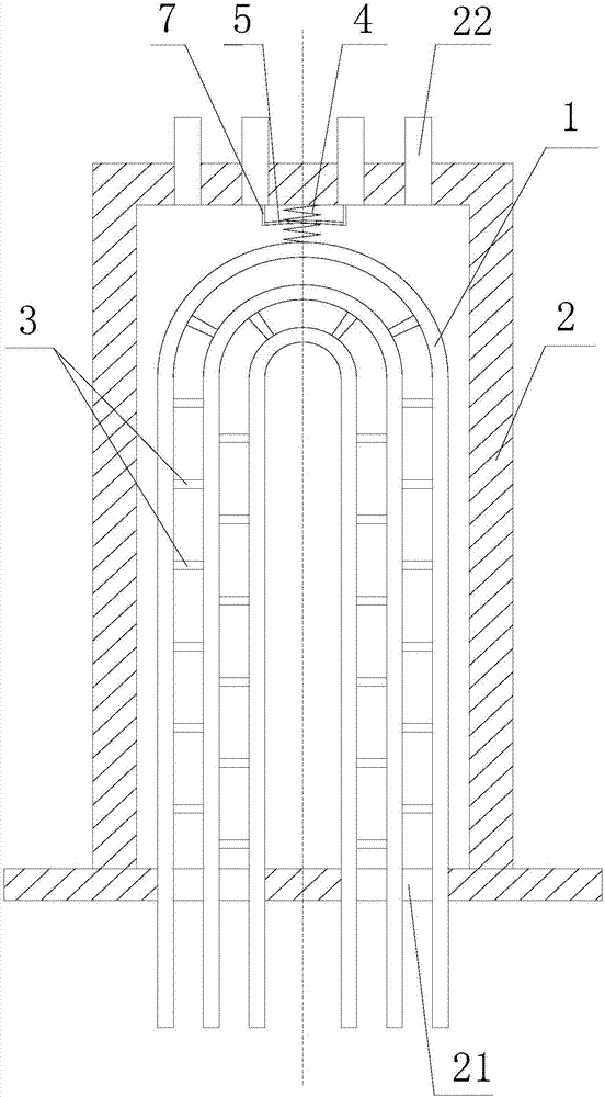
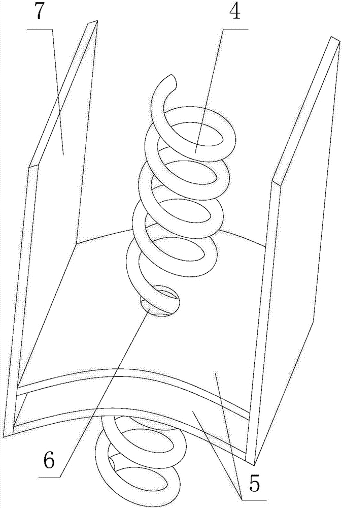
[0022] Such as figure 1 and figure 2 The heat exchange structure of a reactor evaporator shown includes a tube bundle coaming plate 2 and several U-shaped heat transfer tubes 1. The U-shaped heat transfer tubes 1 include straight pipe sections and curved sections. The U-shaped heat transfer tubes 1 The curved section and some straight pipe sections are located inside the tube bundle coaming 2; the tube bundle coaming 2 is also provided with a water inlet flow channel 21 and a water outlet flow channel 22, and two adjacent U-shaped heat transfer tubes 1 are fixed by several connecting rods 3 Connection; also includes a spring 4, one end of the spring 4 is fixedly connected to the inner wall of the tube bundle coaming plate 2, and the other end is fixedly connected to the curved section of the U-shaped heat transfer tube 1, and the axis of the spring 4 and the U-shaped heat transfer tube connected thereto The central symmetry line of 1 is collinear; it also includes a rubber s...


PUM


Abstract

The invention discloses a heat exchange structure of a reactor evaporator. The heat exchange structure comprises a tube bundle coaming, a plurality of U-shaped heat transfer tubes, springs and rubber sheets, wherein the U-shaped heat transfer tubes comprise straight sections and curved sections, and the curved sections and a part of the straight sections of the U-shaped heat transfer tubes are located in the tube bundle coaming; two adjacent U-shaped heat transfer tubes are fixedly connected through a plurality of connecting rods; one end of each spring is fixedly connected to the inner wall of the tube bundle coaming, the other ends of the springs are fixedly connected to the curved sections of the U-shaped heat transfer tubes, and the axis of each spring is collinear with the entrosymmetric line of the U-shaped heat transfer tube connected with the spring; the rubber sheets sleeve the springs, through holes are formed in the rubber sheets, and the aperture of each through hole is greater than the wire diameter of each spring and is less than the outside diameter of each spring; and two opposite sides of the rubber sheets are fixedly connected to the inner wall of the tube bundle coaming through connecting pieces. The heat exchange structure aims to solve the problem of low damping efficiency when an anti-vibration bar is used in the prior art, and the purposes of improving the damping efficiency and prolonging the service life are realized.

Description

technical field [0001] The invention relates to the field of heat transfer of reactor steam generators in nuclear power plants, in particular to a heat exchange structure of reactor evaporators. Background technique [0002] Steam generators are the second most important equipment in nuclear power plants next to pressure vessels. Its function is to transfer the heat from the primary loop water from the nuclear reactor to the secondary loop water and turn it into steam. There are thousands of thin-walled heat transfer tubes inside the steam generator, which can be divided into vertical, inverted U-shaped tubes, and natural circulation steam generators according to the shape of the heat transfer tubes. The water in the primary circuit flows in the heat transfer tube, and the water in the secondary circuit flows outside the tube, so as to exchange heat between the two water flow circuits through the heat transfer tube, and then generate steam on the upper part of the steam gen...

Claims


Application Information

Patent Timeline
Patent Type & Authority Applications(China)
IPC IPC(8): F22B31/08F22B37/20
CPCF22B31/08F22B37/206
Inventor 邓利平
Owner ANHUI KECHUANG INTELLIGENT INTPROP SERVICE CO LTD
Why Eureka
Try Eureka