Tilting auxiliary supporting device

An auxiliary support and disc spring technology, which is applied in the direction of weapon accessories, ammunition storage, ammunition, etc., can solve the problems of time-consuming and labor-intensive, unfavorable management, and affect the efficiency of cargo loading, and achieve a simple structure, low cost, and easy maintenance. Effect

Active Publication Date: 2017-10-03
BEIJING INST OF SPACE LAUNCH TECH +1
View PDF6 Cites 3 Cited by
  • Summary
  • Abstract
  • Description
  • Claims
  • Application Information

AI Technical Summary

Problems solved by technology

The existing transport vehicles mainly have the following problems in practical applications due to the structural defects of their auxiliary support devices: when switching from transporting a certain type of goods to transporting another type of goods, it is necessary to re-install them in the insulation cabin. Install auxiliary support devices matching the goods to be transported to provide support, and need to remove the previous auxiliary support devices to make room. On the one hand, dismantling and moving the auxiliary support devices for many times is not only time-consuming and labor-intensive, but also affects the goods. loading efficiency; on the other hand, it is necessary to provide storage space for different auxiliary support devices and maintain them separately, which is not conducive to management

Method used


Image

  • Tilting auxiliary supporting device
  • Tilting auxiliary supporting device
  • Tilting auxiliary supporting device

Examples


Embodiment Construction

[0019] First of all, it should be explained that the orientation words such as front, back, left, and right in the present invention are only described according to the accompanying drawings for easy understanding, and are not intended to limit the technical solution of the present invention.

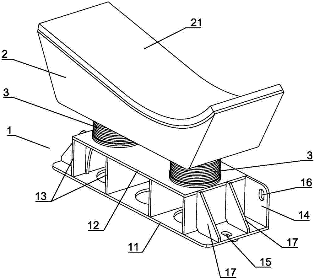
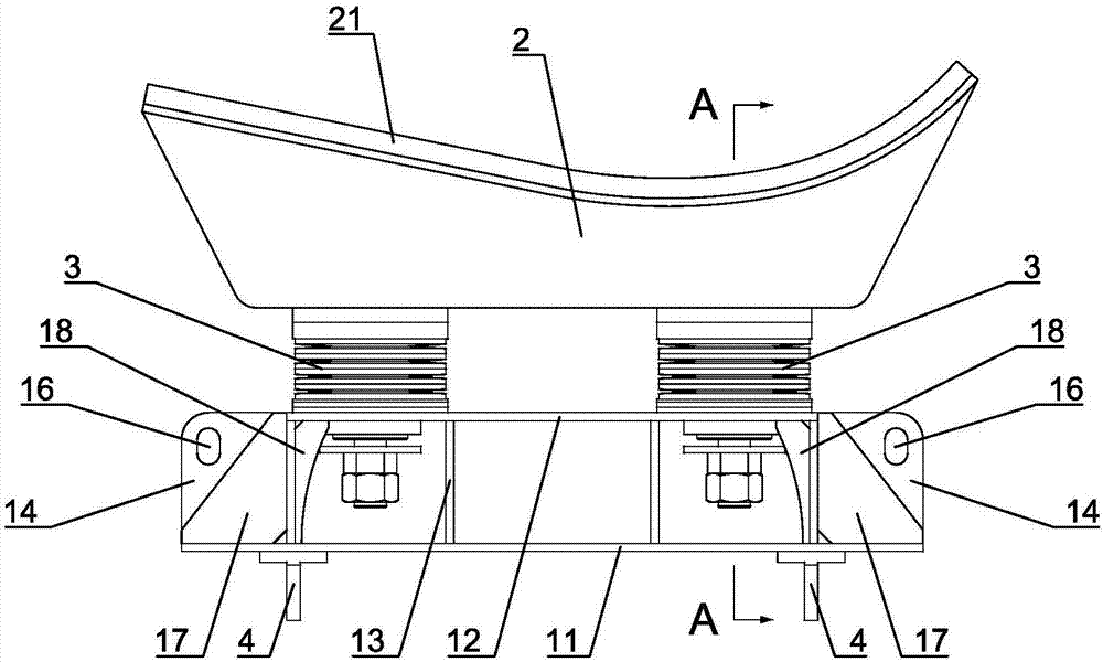
[0020] Such as Figure 1 to Figure 4 Shown is a specific embodiment of a lodging auxiliary support device of the present invention, including a base 1 , a bracket 2 , and two sets of disc spring assemblies 3 arranged between the base 1 and the bracket 2 . The base 1 specifically includes a bottom plate 11 and a top plate 12, the bottom plate 11 and the top plate 12 are fixedly connected by four connecting plates 13 spaced along the left and right directions, and side plates 14 are fixedly arranged on the rear sides of the bottom plate 11, the top plate 12 and the connecting plate 13 . At the same time, a first fixing hole 15 is set on the bottom plate 11, a second fixing hole 16 is set...


PUM


Abstract

The invention relates to a tilting auxiliary supporting device. The tilting auxiliary supporting device comprises a base, a bracket and at least two disc spring assemblies arranged between the base and the bracket. The base comprises a bottom plate and a top plate, and the bottom plate and the top plate are fixedly connected through at least two connecting plates which are distributed at intervals in the horizontal direction. Side plates are fixed to the front sides or the rear sides of the bottom plate, the top plate and the connecting plates. The bottom plate is provided with a first fixing hole. The side plates are provided with second fixing holes. At least two rotation support lugs are fixed on the lower side of the bottom plate and distributed at intervals in the horizontal direction. The rotation support lugs are provided with hinge pin holes. The bottom of the bracket is connected with the upper ends of the disc spring assemblies. The lower ends of the disc spring assemblies are connected with the top plate of the base. The tilting auxiliary supporting device has the advantages of being simple in structure, low in cost and convenient to use and maintain, multiple auxiliary supporting devices can be arranged in an insulating bin at the same time so as to support cargos of different types, and the cargo loading efficiency is effectively improved.

Description

technical field [0001] The invention relates to a support device, in particular to an auxiliary support device for a transport vehicle to support goods. Background technique [0002] In the field of military and aerospace, the transport vehicle belongs to a special vehicle for transporting goods. For special goods such as rockets and missiles, it is necessary to provide a good temperature and humidity environment and a mechanical environment for the transported goods during transportation. At present, in this field, thermal insulation cabins are mainly used and auxiliary support devices are set in the thermal insulation cabins to meet the requirements. Due to the limitation of the volume of the transported goods and the volume of the insulation cabin, the transport vehicle can generally only load one such special cargo at a time; and because the appearance and position of the palm of different types of goods are different, this requires the transport vehicle to transport dif...

Claims


Application Information

Patent Timeline
Patent Type & Authority Applications(China)
IPC IPC(8): F42B39/28
CPCF42B39/28
Inventor 肖勇贾延奎刘奇程明龙王博何冠杰刘洪波姜苏洋
Owner BEIJING INST OF SPACE LAUNCH TECH
Why Eureka
Try Eureka