Sewage treatment device

A technology of sewage treatment device and sewage tank, applied in water/sewage treatment, water/sludge/sewage treatment, mixer with rotating stirring device, etc. Difficulty and other problems, to achieve the effect of improving the efficiency of removing blood stasis, reducing labor intensity, and convenient use

Inactive Publication Date: 2017-10-10
苏州玛斯堡威电子科技有限公司
View PDF0 Cites 3 Cited by
  • Summary
  • Abstract
  • Description
  • Claims
  • Application Information

AI Technical Summary

Problems solved by technology

[0002] In some large factories, a sewage discharge system is specially set up, and the sewage tank is an important part of the sewage system. It is mainly used for centralized storage of sewage, and the purpose of sewage purification is achieved through purification equipment. However, the process of centralized storage of sewage has sedimentation properties. , so that silt is prone to occur in the sewage tank, and it is difficult to discharge normally. In the existing similar phenomena, manual stirring is used to achieve the purpose of removing stasis. However, manual stirring to remove stasis is not only difficult to operate but also inefficient. Fundamentally solve this problem, therefore, there is an urgent need for an intelligent sewage mixing equipment to meet the existing needs

Method used


Image

  • Sewage treatment device
  • Sewage treatment device
  • Sewage treatment device

Examples


Embodiment Construction

[0015] All features disclosed in this specification, or steps in all methods or processes disclosed, may be combined in any manner, except for mutually exclusive features and / or steps.

[0016] Any feature disclosed in this specification (including any appended claims, abstract and drawings), unless expressly stated otherwise, may be replaced by alternative features which are equivalent or serve a similar purpose. That is, unless expressly stated otherwise, each feature is one example only of a series of equivalent or similar features.

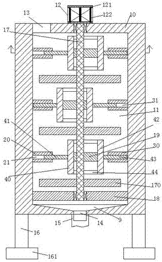
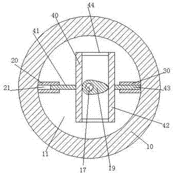
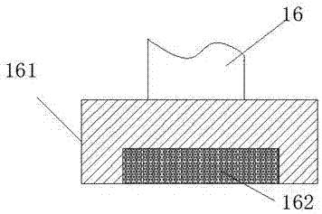
[0017] like Figure 1-3 As shown, a sewage treatment device of the present invention includes a sewage tank 10 fixedly installed on the bottom frame 16, the sewage tank 10 is provided with a stirring chamber 11, and the bottom of the stirring chamber 11 is fixedly equipped with a placement plate 18, A steering shaft 17 is turnably installed between the placement plate 18 and the top wall of the stirring chamber 11, and the upper end of the st...


PUM


Abstract

The invention relates to a sewage treatment device. The sewage treatment device comprises a sewage tank fixedly arranged on an underframe, wherein a stirring cavity is arranged in the sewage tank, a placing plate is fixedly arranged at the bottom of the stirring cavity, a steering shaft is arranged between the placing plate and the top wall of the stirring cavity in a steering way, the upper end of the steering shaft is connected with a motor fixedly arranged at the upper end of the sewage tank, multiple stirring arms and convex wheels are arranged on the steering shaft, orientations of projecting parts of two adjacent convex wheels are opposite, a left guide sliding sleeve and a right guide sliding sleeve which are arranged horizontal to the convex wheels are accordingly arranged on the walls of the left end and the right end of the stirring cavity, a left guide sliding slot and a right guide sliding slot with the oral areas toward the steering shaft are formed in the left guide sliding sleeve and the right guide sliding sleeve respectively, a left guide sliding bar and a right guide sliding bar are arranged in the left guide sliding chute and the right sliding chute smoothly and respectively, and a left push-and-pull plate and a right push-and-pull plate are respectively fixed arranged at one end, toward the steering shaft, of each of the left guide sliding bar and the right guide sliding bar.

Description

technical field [0001] The invention relates to the field of sewage treatment, in particular to a sewage treatment device. Background technique [0002] In some large factories, a sewage discharge system is specially set up, and the sewage tank is an important part of the sewage system. It is mainly used for centralized storage of sewage, and the purpose of sewage purification is achieved through purification equipment. However, the process of centralized storage of sewage has sedimentation properties. , so that silt is prone to occur in the sewage tank, and it is difficult to discharge normally. In the existing similar phenomena, manual stirring is used to achieve the purpose of removing stasis. However, manual stirring to remove stasis is not only difficult to operate but also inefficient. Fundamentally solve this difficult problem, therefore, be badly in need of a kind of intelligent sewage mixing equipment to meet existing demands. Contents of the invention [0003] T...

Claims


Application Information

Patent Timeline
Patent Type & Authority Applications(China)
IPC IPC(8): B01F7/18B01F11/00B01F15/00C02F1/00
CPCC02F1/00B01F31/441B01F27/90B01F35/4111B01F2101/305
Inventor 舒丽燕
Owner 苏州玛斯堡威电子科技有限公司
Why Eureka
Try Eureka