Electronic equipment safe cleaning device

A technology for cleaning devices and electronic equipment, which is applied in the direction of removing smoke and dust, cleaning methods and appliances, and cleaning methods using gas flow, etc. It can solve problems such as hidden dangers in the operation of electronic equipment, low degree of automation, and internal short circuits, so as to prevent the body from being damaged. Damage, high degree of automation, and the effect of preventing dust residue

Active Publication Date: 2017-10-10
JINAN LICHENG POWER SUPPLY CO OF STATE GRID SHANDONG ELECTRIC POWER CO +1
View PDF8 Cites 4 Cited by
  • Summary
  • Abstract
  • Description
  • Claims
  • Application Information

AI Technical Summary

Problems solved by technology

The biggest faults and hidden dangers of electronic equipment come from dust pollution. The light ones affect heat dissipation, and the serious ones cause internal short circuits, which bring extremely serious safety hazards to the operation of electronic equipment.
[0003] The demand for dust cleaning is very large, and electronic equipment needs to be cleaned regularly. The existing cleaning process is manual cleaning. The original way to manually clean the dust is to open the casing of the electronic equipment, use a brush to clean the dust, and then use a fan to blow it. Dust is discharged from electronic equipment, the workload is heavy, and the degree of automation is low; manual cleaning of electronic equipment will cause dust to fly and pollute the environment; manual cleaning will easily cause workers to inhale dust, causing pneumoconiosis occupational diseases

Method used


Image

  • Electronic equipment safe cleaning device
  • Electronic equipment safe cleaning device
  • Electronic equipment safe cleaning device

Examples


Embodiment Construction

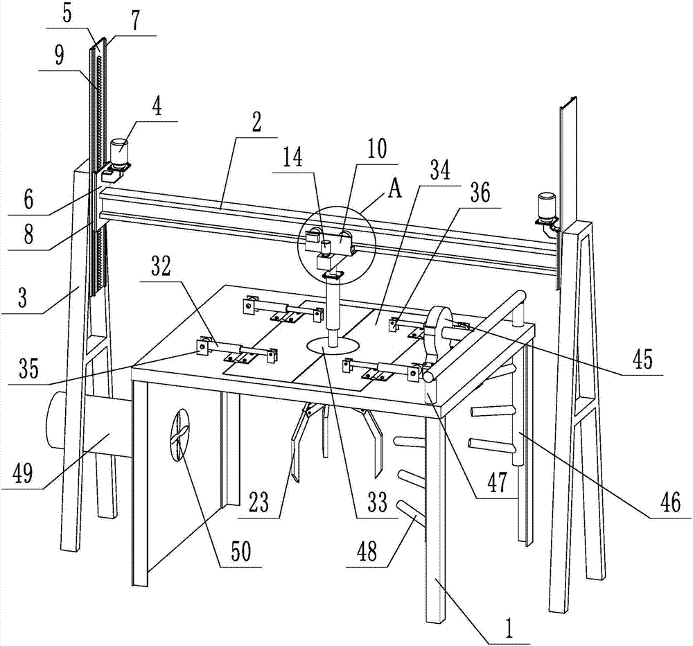
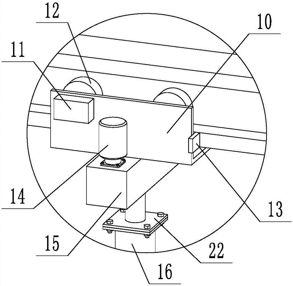
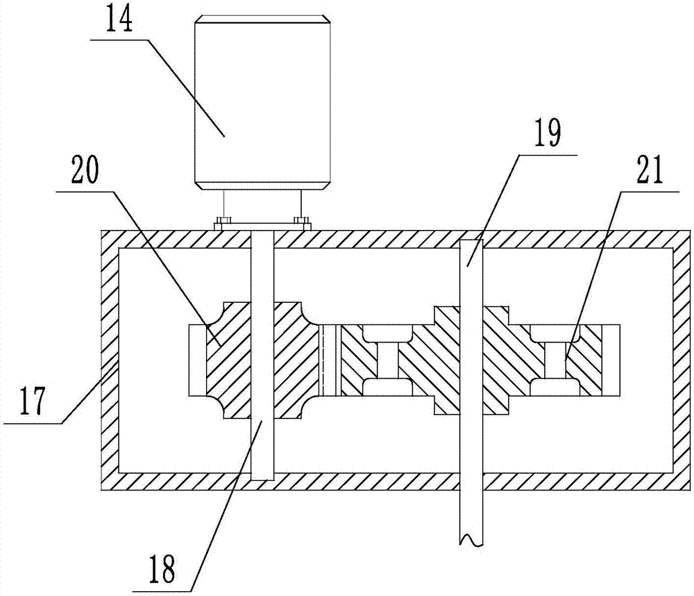
[0040] according to Figure 1 to Figure 6As shown, a safety cleaning device for electronic equipment includes a box body 1, a transport mechanism, an opening and closing mechanism, an air blowing mechanism, a dust collection and discharge mechanism, and monitoring equipment. The opening and closing mechanism, the air blowing mechanism, and the monitoring equipment are supported on the box body 1 Above, the dust collection and discharge mechanism is located at the left end of the box and communicates with the inner cavity of the box. The transportation mechanism includes a beam 2, a support beam 3, a beam lifting mechanism, a walking mechanism, a lifting and rotating mechanism, and a clamping mechanism. The beam 2 and the support beam 3 The sliding connection between them is through the beam lifting mechanism, the traveling mechanism and the lifting and rotating mechanism are supported on the beam 2, and the clamping mechanism is installed at the lower end of the lifting and rot...


PUM


Abstract

The invention discloses an electronic equipment safe cleaning device. The electronic equipment safe cleaning device comprises a box body, a transport mechanism, an opening-closing mechanism, an air blowing mechanism, a dust collecting and discharging mechanism and monitoring equipment; the opening-closing mechanism, the air blowing mechanism and the monitoring equipment are arranged on the box body in a supported manner, and the dust collecting and discharging mechanism is located at the left end of the box body and communicates with an inner cavity of the box body; the transport mechanism comprises a cross beam, supporting beams, cross beam lifting mechanisms, a walking mechanism, a lifting and rotating mechanism and a clamping mechanism, the cross beam and the supporting beams are slidably connected through the cross beam lifting mechanisms, the walking mechanism and the lifting and rotating mechanism are arranged on the cross beam in a supported manner, and the clamping mechanism is installed at the lower end of the lifting and rotating mechanism. By means of the electronic equipment safe cleaning device, the problems of cleaning, collecting and discharging of dust can be solved, harmless safety protection on working personnel is achieved, and safety of electronic equipment is also protected.

Description

technical field [0001] The invention relates to the technical field of cleaning electronic equipment, in particular to a safe cleaning device for electronic equipment. Background technique [0002] At present, the coverage and utilization rate of electronic equipment in power substations, network communication rooms, and telephone exchange rooms are very high, and the requirements for the stable operation of high-end electronic equipment are particularly high, reaching aerospace-level requirements. The biggest failures and hidden dangers of electronic equipment come from dust pollution, which affects heat dissipation in the lightest cases, and causes internal short circuits in severe cases, which brings extremely serious safety hazards to the operation of electronic equipment. [0003] The demand for dust cleaning is very large, and electronic equipment needs to be cleaned regularly. The existing cleaning process is manual cleaning. The original way to manually clean the dus...

Claims


Application Information

Patent Timeline
Patent Type & Authority Applications(China)
IPC IPC(8): B08B5/02B08B15/04
CPCB08B5/02B08B15/04
Inventor 刘勇张鑫刘双喜张阳王世强陈长宇
Owner JINAN LICHENG POWER SUPPLY CO OF STATE GRID SHANDONG ELECTRIC POWER CO
Why Eureka
Try Eureka