Manufacturing method of steam compressor pressure expander

A steam compressor and manufacturing method technology, applied in the field of steam compressors, can solve the problems affecting the diffuser, the deformation of the end face of the diffuser, and the low flatness and verticality of the end face, so as to save milling tooling, ensure the height dimension, The effect of improving the overall quality

Inactive Publication Date: 2017-10-10
CHONGQING JIANGJIN SHIPBUILDING IND
View PDF4 Cites 9 Cited by
  • Summary
  • Abstract
  • Description
  • Claims
  • Application Information

AI Technical Summary

Problems solved by technology

[0004] In the existing diffuser manufacturing method, there are many defects, which are as follows: 1. Due to the control of the throat area of ​​the diffuser, the requirements for the profile of the diffuser blade are high, but the actual processing is completed. The profile of the blade line is poor, which cannot meet the production requirements; 2. In order to better install the diffuser into the steam compressor and better realize the function of the diffuser, it is necessary to strictly control the assembly clearance, b

Method used


Image

  • Manufacturing method of steam compressor pressure expander
  • Manufacturing method of steam compressor pressure expander
  • Manufacturing method of steam compressor pressure expander

Examples


Embodiment Construction

[0039] Embodiments of the present invention will be described in further detail below in conjunction with the accompanying drawings.

[0040] In this embodiment, the orientation or positional relationship indicated by the terms "upper", "lower", "left", "right", "front", "rear", "upper end" and "lower end" are based on the orientation or positional relationship shown in the drawings, It is for the convenience of description only, and does not indicate or imply that the device or element referred to must have a specific orientation, be constructed in a specific orientation, or operate, and thus should not be construed as limiting the present invention.

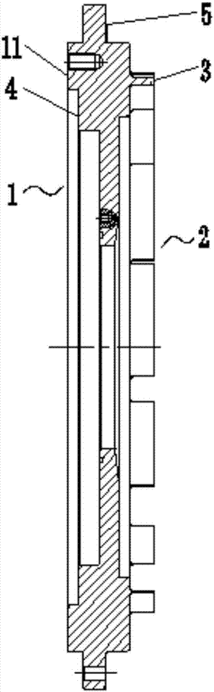
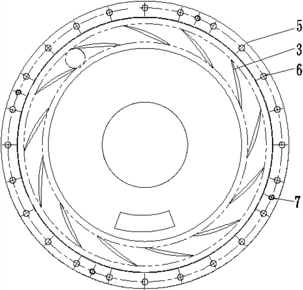
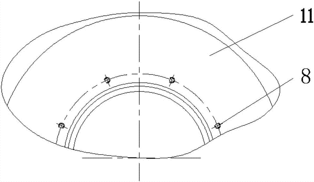
[0041] During specific implementation: if Figure 1 ~ Figure 4 Shown, a kind of manufacturing method of vapor compressor diffuser comprises the following steps:

[0042] a. Blank heat treatment;

[0043] b. Large end 1, outer circle, inner hole and first step surface 4 of rough-turned diffuser;

[0044] c. Small end 2, outer...


PUM


Abstract

The invention discloses a manufacturing method of a vapor compressor diffuser, which comprises the following steps: a. rough heat treatment; b. rough turning of the diffuser big end, outer circle, inner hole and first stepped surface; c. rough turning The small end, outer circle, inner hole and the second step surface of the diffuser; d, the large end, outer circle, inner hole and the first step surface of the semi-finishing diffuser; Milling blades, after finishing milling, send three-coordinate inspection; f, after passing the inspection, finish turning the end surface and inner hole of the small end of the diffuser; g, finishing turning the end surface and inner hole of the large end of the diffuser; h, marking and drilling Use the center line for alignment, drill and tap; i, file and repair the bottom of the blade flow path; j, conduct a penetration test on the blade. The invention has the advantages of high profile of blade profile, high requirements on flatness and verticality of end faces, and good process performance.

Description

technical field [0001] The invention relates to the technical field of steam compressors; in particular, it relates to a method for manufacturing a diffuser of a steam compressor. Background technique [0002] The steam compressor is the key equipment for the heat recovery system to increase the steam temperature and pressure by compressing the steam generated. Its function is to pressurize and heat up low-pressure or low-temperature steam to meet the temperature and pressure requirements required by the process or project. Its working principle is that the compressor impeller rotates on the shaft of the compressor, the gas entering the compressor impeller is rotated, and then enters the diffuser, where the kinetic energy of the gas is converted into the required pressure energy. [0003] A vapor compressor consists of two aspects, a rotor and a stator. The rotor is composed of impeller, main shaft, balance disk, thrust disk and other components, and the stator is composed...

Claims


Application Information

Patent Timeline
IPC IPC(8): B23P15/00
CPCB23P15/00
Inventor 廖文龙段昌文徐海燕
Owner CHONGQING JIANGJIN SHIPBUILDING IND
Why Eureka
Try Eureka