
A pcb automatic punching device and method suitable for baking needs

A technology of stamping device and PCB board, applied in the directions of printed circuit, electrical components, metal processing, etc., can solve the problems of not proposing PCB board detection, unable to guarantee whether the PCB board is qualified or not, and achieve the effect of simple operation

Active Publication Date: 2019-01-29
厦门利德宝电子科技股份有限公司
View PDF1 Cites 0 Cited by
  • Summary
  • Abstract
  • Description
  • Claims
  • Application Information

AI Technical Summary

Problems solved by technology

[0003] The application number is 201220242320.4, which discloses an automatic stamping device for PCB boards, which provides a feeding device in front of the stamping die, and a plate cutting machine in the back, so that the PCB board can be punched and cut at one time, greatly An automatic stamping device for PCB boards that improves production efficiency and safety. However, some existing PCB boards need to be baked first and then stamped. However, an automatic stamping device for PCB boards with application number 201220242320.4 also There is no proposal to test the stamped PCB board, and it is impossible to guarantee whether the stamped PCB board is qualified. Therefore, we propose a PCB automatic stamping device and method suitable for baking needs to solve the above-mentioned problems.

Method used


Image

  • A pcb automatic punching device and method suitable for baking needs
  • A pcb automatic punching device and method suitable for baking needs
  • A pcb automatic punching device and method suitable for baking needs

Examples


Embodiment

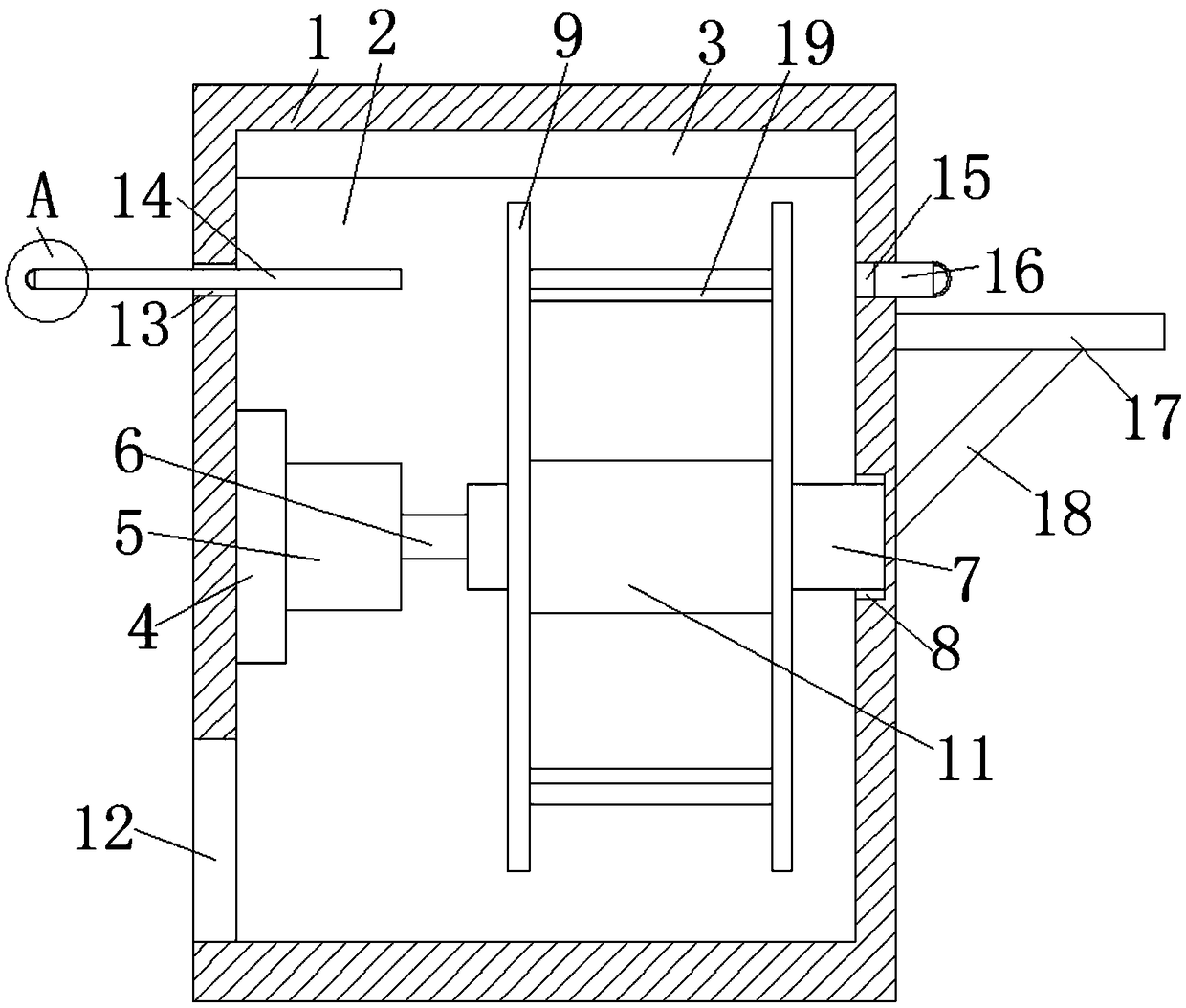
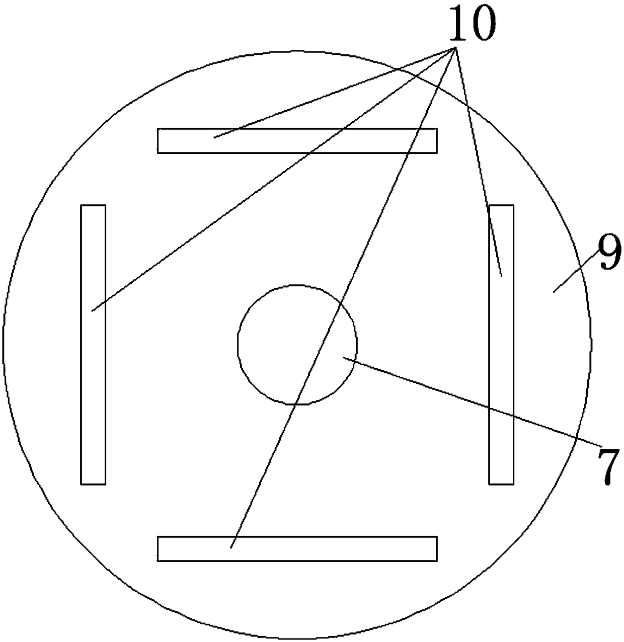
[0036]Referring to 1-6, the present embodiment proposes a PCB automatic stamping device suitable for baking needs, including a baking mechanism and a stamping mechanism, and the baking mechanism includes a retrieving module, a baking module and a first conveying module. module, and the baking module includes a baking box 1 and a placement plate 17, the baking box 1 is provided with a baking chamber 2, and the top inner wall of the baking chamber 2 is provided with a heating pipe 3, and the baking chamber 2 A stepping motor 5 is fixedly installed on the inner wall of one side of the stepping motor 5, and a connecting shaft 6 is welded on the output shaft of the stepping motor 5, and a rotating shaft 7 is welded on the end of the connecting shaft 6 away from the stepping motor 5, and the other end of the baking chamber 2 A groove 8 is opened on the inner wall of one side, and the rotating shaft 7 is rotatably installed in the groove 8. The outer fixed sleeve of the rotating shaft...


PUM


Abstract

The invention discloses an automatic punching system and an automatic punching method suitable for PCBs (Printed Circuit Board) with baking requirements. The system comprises a baking mechanism and a punching mechanism, wherein the baking mechanism comprises a material taking module, a baking module and a first conveying module, the baking module comprises an oven and a placing plate, a baking chamber is formed in the oven, a heating pipe is arranged on the inner wall of the top of the baking chamber, a stepping motor is fixedly installed on the inner wall of one side of the baking chamber, a connecting shaft is welded on an output shaft of the stepping motor, a rotating shaft is welded to one end, which is far from the stepping motor, of the connecting shaft, a groove is formed in the inner wall of the other side of the baking chamber, and the rotating shaft is rotatably installed in the groove. The automatic punching system has the advantages of economy, practicability and simplicity in operation; the PCBs are baked by the oven, then the PCBs are detected by virtue of a detection module, and finally, the PCBs are punched and cooled, so that the required PCBs can be obtained; and whether the product quality is qualified can be automatically detected.

Description

technical field [0001] The invention relates to the technical field of PCB board processing equipment, in particular to a PCB automatic stamping device and method suitable for baking needs. Background technique [0002] PCB circuit board, also known as printed circuit board, is a provider of electrical connections for electronic components. Its development has a history of more than 100 years. Its design is mainly layout design. The main advantage of using circuit boards is that it greatly reduces wiring and Assembly errors increase the level of automation and productivity. [0003] The application number is 201220242320.4, which discloses an automatic stamping device for PCB boards, which provides a feeding device in front of the stamping die, and a plate cutting machine in the back, so that the PCB board can be punched and cut at one time, greatly An automatic stamping device for PCB boards that improves production efficiency and safety. However, some existing PCB boards ...

Claims


Application Information

Patent Timeline
Patent Type & Authority Patents(China)
IPC IPC(8): B26F1/40B26D7/00B26D5/00B26D7/06B26D7/32H05K3/00
CPCB26D5/005B26D7/00B26D7/06B26D7/32B26F1/40H05K3/00
Inventor 江东红曹克铎吴志峰
Owner 厦门利德宝电子科技股份有限公司
Learn More