High-flow pressure stabilizer

A voltage stabilizing device and high-flow technology, applied in the field of sanitary ware, can solve problems such as inability to use, and achieve the effects of saving costs, saving transfer space, and reducing transfer risks

Active Publication Date: 2017-10-10
BESTTER XIAMEN TECH
View PDF10 Cites 2 Cited by
  • Summary
  • Abstract
  • Description
  • Claims
  • Application Information

AI Technical Summary

Problems solved by technology

But with this structure, when the water pressure is high, the valve core will block the cone hole and cannot be used.

Method used


Image

  • High-flow pressure stabilizer
  • High-flow pressure stabilizer
  • High-flow pressure stabilizer

Examples


Embodiment Construction

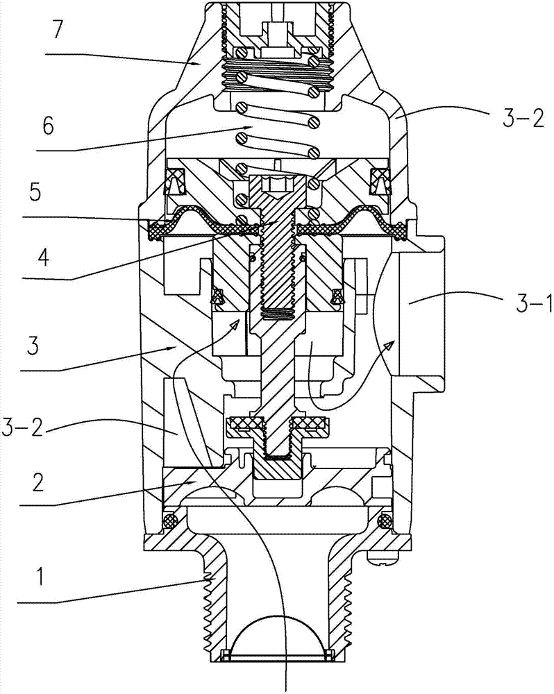
[0036] For specific embodiments of the present invention, refer to Figure 1 to Figure 3 , a large flow voltage stabilizing device, mainly composed of a water inlet joint 1, a sealing bracket 2, a body 3, a piston assembly 4, a stabilizing diaphragm 5, a stabilizing spring 6, and a gland 7.

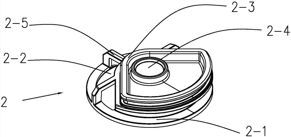
[0037] see image 3 , the seal bracket 2 includes a disc-shaped seat body 2-1, the center of the seat body 2-1 is provided with a piston rod movable jack 2-4, and the left side of the piston rod movable jack 2-4 is provided with a water hole 2- 2. A sealing ring 2-3 protruding from the upper surface of the base body is provided between the water passage hole 2-2 and the piston rod movable socket 2-4. In this embodiment, the sealing ring surrounds the area of ​​the movable socket 2-4 of the piston rod. In this embodiment, a reinforcing rib 2-5 is also provided, the left end of the reinforcing rib 2-5 extends upward from the upper surface of the seat body 2-1 on the left side of the water...


PUM


Abstract

The invention discloses a high-flow pressure stabilizer. The high-flow voltage stabilizer includes a cylindrical body (3) and a piston assembly (4) which is arranged in the body (3), and the high-flow voltage stabilizer is characterized in that the water inlet end of the body (3) is provided with a sealed support (2); the sealed support (2) includes a disc-shaped base (2-1); the body (3) includes a cylindrical outer cylinder (3-0), and an inner cylinder (3-3) is arranged in the outer cylinder (3-0); the lower end of the inner cylinder is located certain distance away from the upper surface of the sealed support (2); a retaining wall (3-7) which extends downwards is arranged at the end of one side of the inner cylinder, and the retaining wall is inserted between a water discharge hole area of the sealed support (2) and a sealed area of the sealed support (2); the piston assembly (4) includes a piston rod (4-4), and at least one middle sealed body (4-1) and one lower sealed body (4-5) which move synchronously are arranged on the piston rod (4-4). The high-flow voltage stabilizer further includes a piston restoring unit. The high-flow voltage stabilizer can achieve voltage stabilization under high flow.

Description

technical field [0001] The invention relates to the field of sanitary ware, in particular to a water flow stabilizing device. Background technique [0002] In the tankless smart toilet, considering the flushing ability and flushing experience at low water pressure, the product is required to have a pressure stabilizing device with a large flow waterway. [0003] The cover plate needs to be located above the toilet, and the water inlet pipe enters the water system inside the cover plate from the bottom of the toilet. A pressure stabilizing device needs to be installed in the waterway system in order to maintain a stable flushing water pressure. However, the water inlet and outlet directions of existing voltage stabilizing products are the same, so that the built-in voltage stabilizing device needs to take up a lot of space, and it is also necessary to add a waterway transfer and reversing mechanism. This not only makes the product very bulky and bulky, but also increases th...

Claims


Application Information

Patent Timeline
Patent Type & Authority Applications(China)
IPC IPC(8): E03D9/16
CPCE03D9/16Y02E10/20
Inventor 龚斌华刘晖明
Owner BESTTER XIAMEN TECH
Why Eureka
Try Eureka