Steel wire rope hook splicing structure and method of prefabricated concrete wall panels
A technology of prefabricated concrete and prefabricated components, which is applied to building components, walls, building structures, etc., can solve the problems of low grouting sleeve construction efficiency, difficult transportation and hoisting operations, and large on-site wet workload. and hoisting operations, reducing the risk of cracking and reducing the amount of work
- Summary
- Abstract
- Description
- Claims
- Application Information
AI Technical Summary
Problems solved by technology
Method used
Image
Examples
Embodiment 1
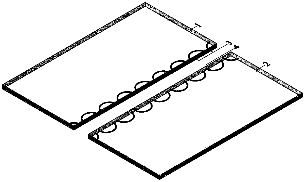
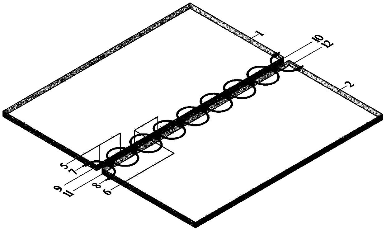
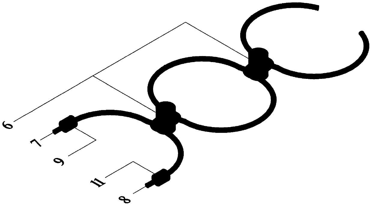
[0034] Such as Figure 4 As shown, it is a slab-slab splicing structure within a span, and the splicing objects are prefabricated floor 1-1 spliced within a span and prefabricated floor 2 spliced within a span 2-1, prefabricated floor 1-1 spliced within a span and prefabricated floor spliced within a span The floor plate two 2-1 is respectively provided with a plurality of smooth and curved first rope-through holes 3 and second rope-through holes 4 inwardly from the splicing edge (see details). figure 1). Since the slabs are spliced across the span, the first rope-threading hole 3 and the second rope-threading hole 4 are respectively located below the midplane of the spliced prefabricated floor 1-1 within the span and the prefabricated floor 2 2-1 spliced across the span. This ensures that the first steel wire rope 7 and the second steel wire rope 8 inserted later can effectively resist the action of the downward bending moment at the splicing part.
[0035] Be...
Embodiment 2
[0037] Such as Figure 5 As shown, it is a splicing structure at the slab support, and the splicing objects are splicing prefabricated floor 1-2 at the support and prefabricated floor 2 2-2 at the support, splicing prefabricated floor 1-2 and Splicing the prefabricated floor 2 2-2 at the support is respectively provided with several smooth curve-shaped first stringing holes 3 and second stringing holes 4 inwardly from the splicing edge (see details). figure 1 ). Due to the splicing connection at the slab support, the first stringing hole 3 and the second stringing hole 4 are above the middle planes of the spliced prefabricated floor 1-2 at the support and the spliced prefabricated floor 2 2-2 at the support respectively position, so as to ensure that the first steel wire rope 7 and the second steel wire rope 8 that are inserted later can effectively resist the downward bending moment of the splicing position.
[0038] Before the splicing and assembly, the first rope hole...
Embodiment 3
[0040] Such as Figure 6 As shown, it is a wall vertical splicing structure, and the splicing objects are vertically splicing prefabricated wall panels 1-3 and vertically splicing prefabricated wall panels 2-3, vertically splicing prefabricated wall panels 1-3 and vertical To the splicing prefabricated wall panel two 2-3, be respectively provided with the first threading hole 3 of several smooth curves and the second threading hole 4 (see details) inwardly from the splicing edge figure 1 ). Preferably, the first stringing hole 3 and the second stringing hole 4 are respectively located at the midplanes of the vertically spliced prefabricated wall panel one 1-3 and the vertically spliced prefabricated wall panel two 2-3.
[0041] Before splicing and assembling, first go around and pass through the first wire rope 7 in the first stringing hole 3 and the second stringing hole 4 of the vertical splicing prefabricated wall panel 1-3 and the vertical splicing prefabricated wall ...
PUM
 Abstract
Description
Claims
Application Information
 - R&D
- Intellectual Property
- Life Sciences
- Materials
- Tech Scout
- Unparalleled Data Quality
- Higher Quality Content
- 60% Fewer Hallucinations
Browse by: Latest US Patents, China's latest patents, Technical Efficacy Thesaurus, Application Domain, Technology Topic, Popular Technical Reports.
© 2025 PatSnap. All rights reserved.Legal|Privacy policy|Modern Slavery Act Transparency Statement|Sitemap|About US| Contact US: help@patsnap.com


