
Arm used for variable nozzle mechanism, variable nozzle mechanism, and turbocharger

A variable, nozzle technology, applied in the direction of machines/engines, mechanical equipment, combustion engines, etc., to achieve the effect of inhibiting wear

Active Publication Date: 2017-10-10
TOYOTA IND CORP
View PDF8 Cites 3 Cited by
  • Summary
  • Abstract
  • Description
  • Claims
  • Application Information

AI Technical Summary

Problems solved by technology

However, in order to suppress oversupply delay (supercharging delay) or exhaust failure caused by poor positional accuracy of the nozzle vanes, the variable nozzle mechanism requires further reduction in wear of the arm and the unison ring, and the existing variable nozzle mechanism Far from being adequate, there is room for further improvement

Method used


Image

  • Arm used for variable nozzle mechanism, variable nozzle mechanism, and turbocharger
  • Arm used for variable nozzle mechanism, variable nozzle mechanism, and turbocharger
  • Arm used for variable nozzle mechanism, variable nozzle mechanism, and turbocharger

Examples


Embodiment Construction

[0024] Hereinafter, embodiments of the present invention will be described in detail with reference to the drawings. It should be noted that the same reference numerals are attached to the same or corresponding parts in the drawings, and the description thereof will not be repeated.

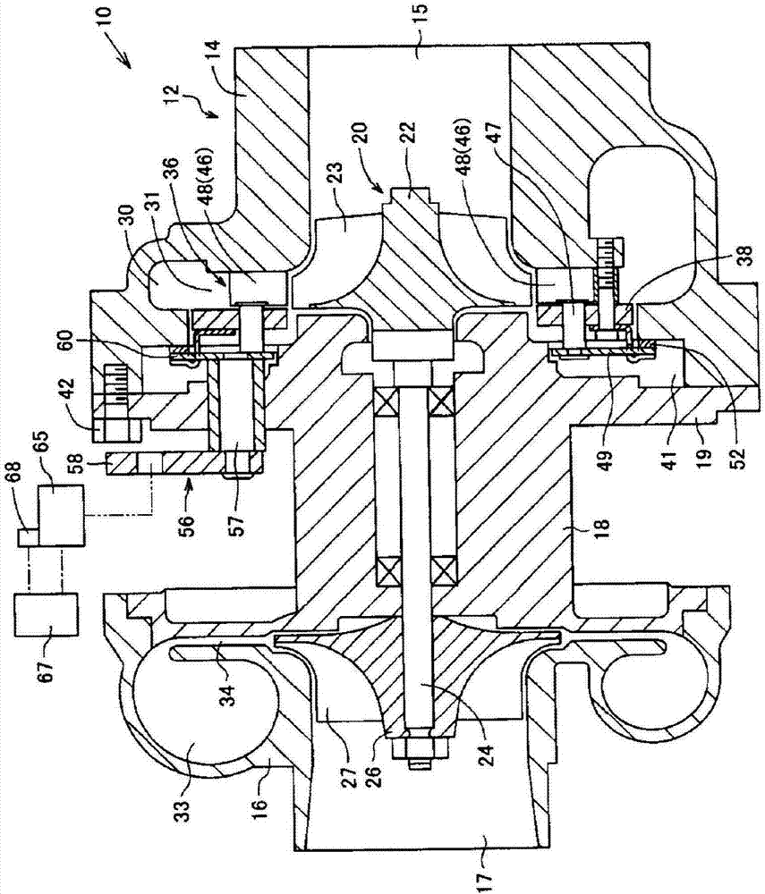
[0025] First, the overall structure of the variable nozzle turbocharger 10 will be described. In addition, in this embodiment, the variable nozzle turbocharger 10 mounted in the internal combustion engine mounted in a vehicle is demonstrated as an example. figure 1 is a sectional view of the variable nozzle turbocharger 10 along the rotation axis.

[0026] Such as figure 1 As shown, the variable nozzle turbocharger 10 includes a rotor 20 . The rotor 20 is rotatably accommodated in the rotor housing 12 . The rotor housing 12 has three housings: a turbine housing 14 , a compressor housing 16 , and a center housing 18 . The center housing 18 connects the turbine housing 14 and the compressor ho...


PUM


Abstract

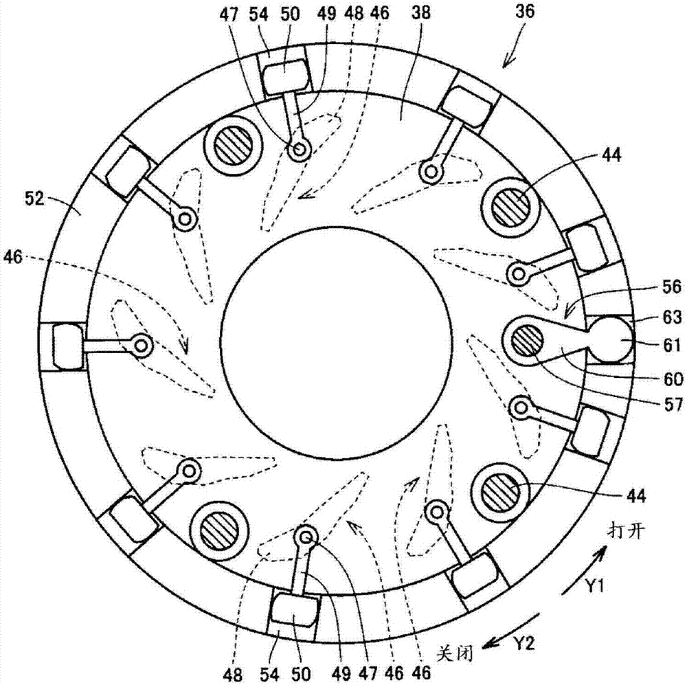
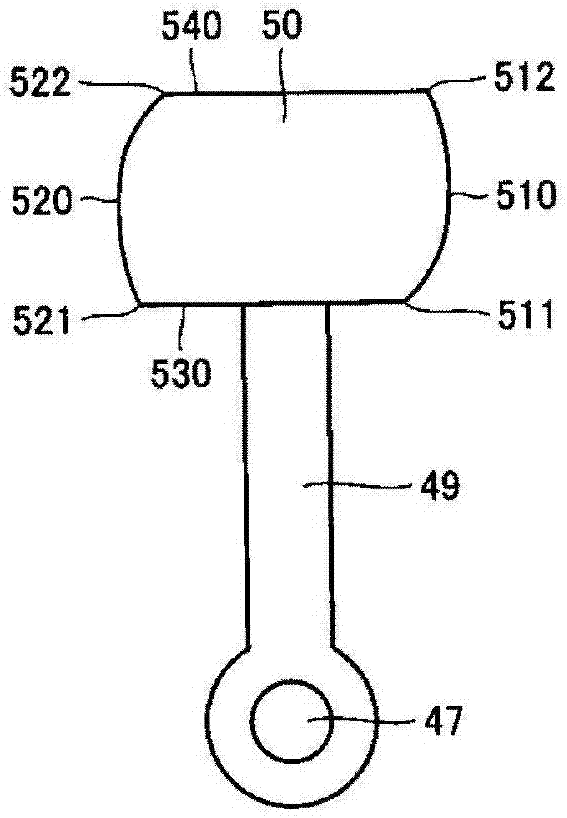
There is provided a variable nozzle mechanism that can suppress wear. The variable nozzle mechanism includes a plurality of nozzle vanes, a plurality of arms (49), and a unison ring. The plurality of nozzle vanes are provided in the nozzle path. The plurality of arms each have a pivoted end and a free end, and the pivoted end is integrally coupled with the nozzle vane by means of a pivot (47). The unison ring is provided with a plurality of grooves. Each groove is engaged with the respective free end of the arm. The free end of the arm has a closing-side contact surface (510) and an opening-side contact surface (520) each in contact with a respective one of paired walls forming the groove of the unison ring. The closing-side contact surface (510) has a curvature different between a side closer to the pivot (47) and a side farther away from the pivot (47).

Description

technical field [0001] The present invention relates to an arm used in a variable nozzle mechanism, the variable nozzle mechanism, and a turbocharger provided with the variable nozzle mechanism. Background technique [0002] The turbocharger injects the exhaust gas in the scroll passage to the turbine wheel, thereby driving the turbine wheel to rotate. Conventionally, in a turbocharger, a variable nozzle mechanism has been employed in order to vary the characteristics of the turbocharger. The variable nozzle mechanism controls the flow velocity of the exhaust gas injected to the turbine wheel by increasing or decreasing the flow path cross-sectional area of ​​the exhaust gas by moving the plurality of nozzle vanes. [0003] Japanese Unexamined Patent Application Publication No. 2014-224498 (Patent Document 1) proposes a variable nozzle mechanism in which an arm fitting groove in which an arm of a variable nozzle engages is formed as a unison ring (unison ring). The wall su...

Claims


Application Information

Patent Timeline
IPC IPC(8): F01D17/16F02B37/24
CPCF01D17/165F02B37/24F05D2220/40Y02T10/12
Inventor 秋本健太
Owner TOYOTA IND CORP
Learn More