A clamping force test tool for isolating switch

A technology for testing tooling and isolating switches, applied to measuring devices, force/torque/work measuring instruments, instruments, etc., can solve problems such as unrealistic clamping force, large measurement errors, and inability to fix the second extrusion part, etc. Achieve the effect of reducing measurement error and ensuring assembly accuracy

Active Publication Date: 2019-09-13
HENAN PINGGAO ELECTRIC +2
View PDF7 Cites 0 Cited by
  • Summary
  • Abstract
  • Description
  • Claims
  • Application Information

AI Technical Summary

Problems solved by technology

During use, it was found that since the pressure sensor needs to be installed first, after the pressure sensor is installed, the three threaded holes on it must correspond to the screw holes on the second extrusion part, so that the second extrusion part can be fixed on the pressure sensor. Otherwise, once the holes are staggered, the second extruded part cannot be fixed
At the same time, the depth at which the pressure sensor is screwed into the first extruded part will affect the cylindricity of the circumference formed by the first extruded part and the second extruded part after assembly. Unable to simulate the most realistic static contact shape
[0004] Therefore, when the pressure sensor needs to meet the threaded hole corresponding to the screw hole on the second extrusion part, the angle of each rotation must be 120 degrees. In practical applications, the threaded joint of the pressure sensor used is usually M4 The thread has a pitch of 0.7mm. When the pressure sensor rotates 120 degrees, its screw-in length is one-third of 0.7mm, which is 0.23mm. Therefore, during the screw-in process of the pressure sensor, the influence on the above-mentioned circumference diameter is 0.23, 0.46, 0.7mm, and the diameter tolerance of the real static contact is generally within 0.05mm, far exceeding this allowable tolerance, so the diameter of the circle formed by the first extrusion part and the second extrusion part is If it cannot be precisely controlled, then the clamping force measured by the measuring device is not the most realistic, and there is a large measurement error

Method used


Image

  • A clamping force test tool for isolating switch
  • A clamping force test tool for isolating switch
  • A clamping force test tool for isolating switch

Examples


Embodiment Construction

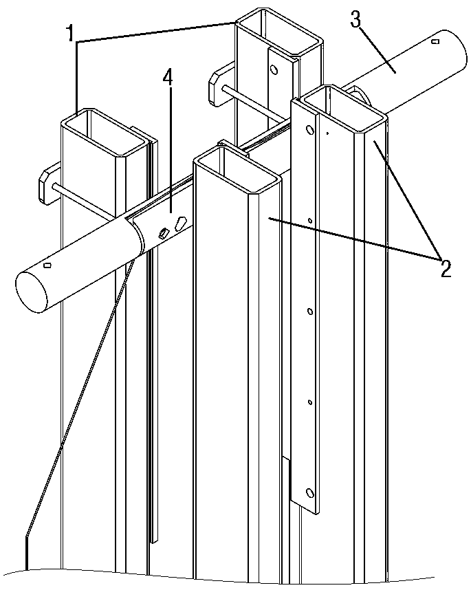
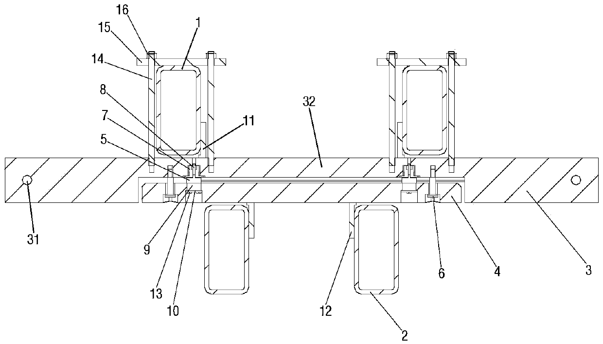
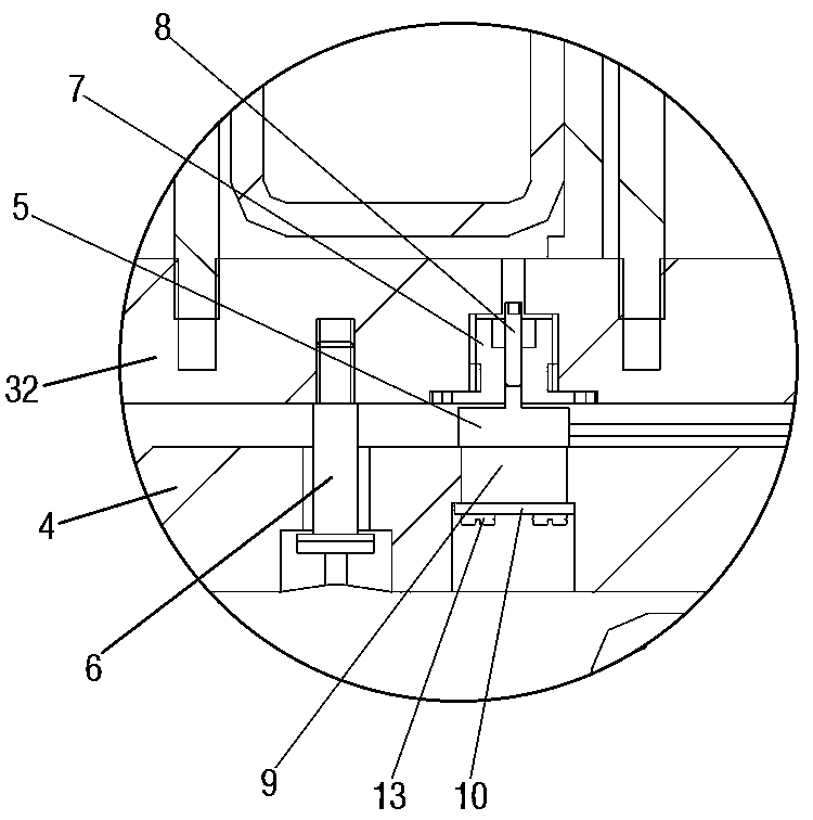
[0039] Embodiment 1 of the clamping force test tooling for the isolating switch is as Figure 1~Figure 17 As shown, the test tooling is made of an aluminum rod which is turned and then cut by wire cutting. The hardness of the aluminum rod is similar to that of the real static contact made of red copper, and it is not easy to damage the moving contact, so it can better simulate The working condition of the real static contact, and the price is relatively cheap. The cut aluminum bar includes a column body 3 and a second extruded portion 4 with an arcuate cross section, and the column body 3 includes a first extruded portion 32 with an arcuate cross section and cylinders located at both ends of the first extruded portion 32 ( That is, the limiting cylinder 33). The bowstring parts of the first extruding part 32 and the second extruding part 4 are arranged oppositely, and a pressure sensor 5 is arranged between them. The pressure sensor 5 has a first force-bearing surface and a s...


PUM


Abstract

The invention provides an isolating switch applied clamping force testing tool, which comprises a first extruding part and a second extruding part which are both arc-shaped in cross section. The bowstring parts of the two extruding parts are arranged oppositely with a pressure sensor between them. The pressure sensor is provided with a threaded joint on a first pressure receiving face, and a threaded hole on a second pressure receiving face. The pressure sensor and the second extruding part are fixedly connected by a fastener; the second extruding part is provided with a rotating structure enabling the fastener to correspond to the threaded hole through rotation after the pressure sensor is connected to the first extruding part. The beneficial effect of the present invention is that when the pressure sensor is connected with the first extruding part, the fastener can correspond to the threaded hole on the pressure sensor through rotation in the rotating structure to realize the connection of the second extruding part with the pressure sensor. The arrangement of the rotating structure weakens the influence of the precession angle of the pressure sensor on the second extruding part by means of the fastener so as to ensure the assembly precision of the testing tool and to reduce the measurement error.

Description

technical field [0001] The invention relates to a clamping force testing tool for an isolating switch. Background technique [0002] The current high-voltage AC isolating switch products, such as scissor-type isolating switch, clamp-type isolating switch, etc., need to measure the clamping force between the dynamic and static contacts when the factory test is completed after assembly. A clamping force measurement device capable of simulating the shape of a static contact is needed. The Chinese invention patent with the authorized announcement number CN103217245B and the authorized announcement date of 2016.03.09 discloses a clamping force measuring device for disconnectors. The device includes a first extrusion part and a second extrusion part with bow-shaped cross sections. , the bowstring parts of the two extruding parts are oppositely arranged, and a pressure sensor is arranged between them, and the two force-bearing surfaces of the pressure sensor are respectively fixed...

Claims


Application Information

Patent Timeline
Patent Type & Authority Patents(China)
IPC IPC(8): G01L5/00
Inventor 李宇鹏庞庆平齐凯陈明王红敏刘拥军崔文霞温铭丽
Owner HENAN PINGGAO ELECTRIC
Why Eureka
Try Eureka