
Laser speckle optometry machine for ophthalmology

A laser speckle and ophthalmology technology, applied in the field of vision detection, can solve the problems of high price, lack of optometry, complicated operation, etc., and achieve the effect of convenient observation and optometry, increasing practicability and increasing comfort

Active Publication Date: 2021-02-09
钟青松
View PDF6 Cites 0 Cited by
  • Summary
  • Abstract
  • Description
  • Claims
  • Application Information

AI Technical Summary

Problems solved by technology

[0002] Optometry is to check the aggregation of light after it enters the eyeball. It takes the emmetropic eye state as the standard to measure the degree of vergence difference between the eye under test and the emmetropic eye. In the actual optometry process, it is mainly to check the deformation of the eyeball. There are two methods, one is to check with an instrument, which can preliminarily measure the deformation of the eyeball, and the other is to try on the lens and wear a pair of glasses with interchangeable lenses to determine the degree of glasses that need to be worn. In the ophthalmology department of the hospital , generally use instrument optometry, but this type of instrument is often fixed in structure, not easy to move, and the operation is more complicated, which requires the cooperation between medical personnel and ophthalmological patients to complete, and it is highly professional. There is no one on the market that can facilitate patients An optometry machine for self-use and optometry, and the general optometry machine is expensive, not suitable for patients to use and purchase alone, and can only be supplied to eye hospitals or various optical shops, which has certain limitations

Method used


Image

  • Laser speckle optometry machine for ophthalmology
  • Laser speckle optometry machine for ophthalmology
  • Laser speckle optometry machine for ophthalmology

Examples


Embodiment Construction

[0014] The following will clearly and completely describe the technical solutions in the embodiments of the present invention with reference to the accompanying drawings in the embodiments of the present invention. Obviously, the described embodiments are only some, not all, embodiments of the present invention. Based on the embodiments of the present invention, all other embodiments obtained by persons of ordinary skill in the art without making creative efforts belong to the protection scope of the present invention.

[0015] In the description of the present invention, it should be noted that the terms "upper", "lower", "inner", "outer", "front end", "rear end", "both ends", "one end", "another end" The orientation or positional relationship indicated by etc. is based on the orientation or positional relationship shown in the drawings, and is only for the convenience of describing the present invention and simplifying the description, rather than indicating or implying that ...


PUM


Abstract

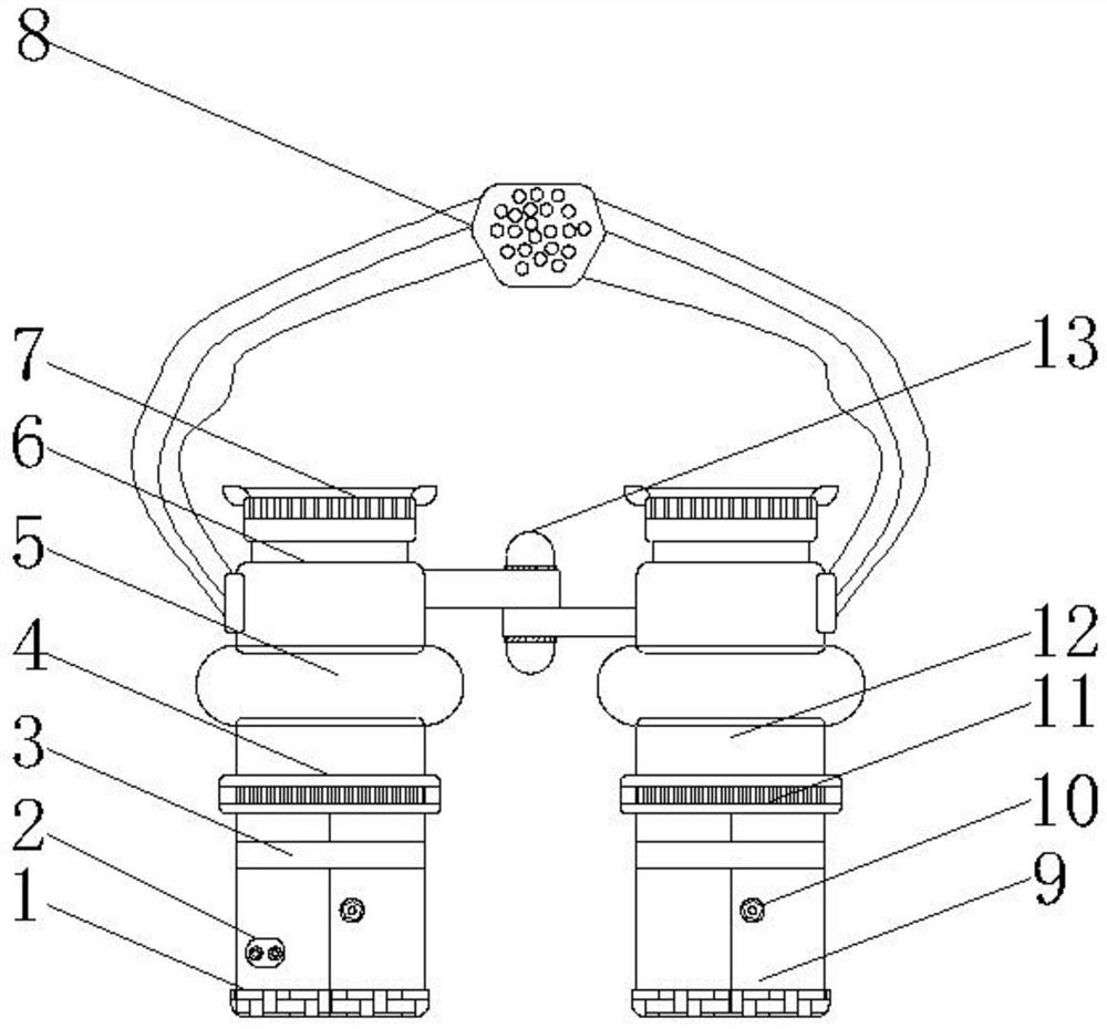
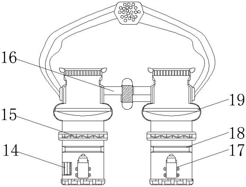
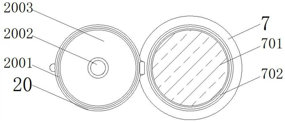
The invention discloses a laser speckle optometry machine for ophthalmology, which comprises a right light source cylinder body, a fixed cylinder body and a left light source cylinder body. Visible light semiconductor lasers are installed inside the right light source cylinder body and the left light source cylinder body. Both the right light source cylinder and the left light source cylinder above the visible light semiconductor laser are equipped with beam expander screens, and the bottom ends of the right light source cylinder and the left light source cylinder are equipped with shading plates, and the right light source cylinder and the left The top of the light source cylinder is equipped with a spiral frame, the surface of the spiral frame is equipped with a toggle gear, the top of the spiral frame is installed with a soft rubber sleeve, and the surface of the fixed cylinder is equipped with a connecting plate. Optometry eyepieces are installed on the top of the fixed cylinder. The invention is provided with a series of structures, so that the optometry machine is easy to carry and wear when used, and has strong applicability, which is convenient for ophthalmology patients to do optometry by themselves, increases wearing comfort, and can detect red-green color blindness.

Description

technical field [0001] The invention relates to the technical field of vision detection, in particular to a laser speckle optometry machine for ophthalmology. Background technique [0002] Optometry is to check the aggregation of light after it enters the eyeball. It takes the emmetropic eye state as the standard to measure the degree of vergence difference between the eye under test and the emmetropic eye. In the actual optometry process, it is mainly to check the deformation of the eyeball. There are two methods, one is to check with an instrument, which can preliminarily measure the deformation of the eyeball, and the other is to try on the lens and wear a pair of glasses with interchangeable lenses to determine the degree of glasses that need to be worn. In the ophthalmology department of the hospital , generally use instrument optometry, but this type of instrument is often fixed in structure, not easy to move, and the operation is more complicated, which requires the c...

Claims


Application Information

Patent Timeline
Patent Type & Authority Patents(China)
IPC IPC(8): A61B3/10A61B3/103
CPCA61B3/0008A61B3/10A61B3/103
Inventor 钟青松张顺
Owner 钟青松
Learn More