OPLC (Optical Power Line Communication) terminal stripping and fixing seal device and process thereof

A sealing device and terminal technology, applied in the direction of light guide, optics, instruments, etc., can solve the problems of optical cable exposure, poor anti-damage ability, easy to be affected by moisture and aging at the stripping branch, and achieve the effect of convenient operation and strong overall strength

Pending Publication Date: 2017-10-10
ZTT ELECTRICAL TECH CO LTD +1
View PDF9 Cites 4 Cited by
  • Summary
  • Abstract
  • Description
  • Claims
  • Application Information

AI Technical Summary

Problems solved by technology

In the process of implementing power optical fiber into the home, there is a problem of OPLC connection. In the local power distribution cabinet, building power distribution cabinet, floor power distribution cabinet and other devices, it is necessary to peel off the OPLC sheath and distribute and connect the cables and optical cables respectively. It will cause damage to the outer sheath of OPLC and exposure of cables and optical cables, and it will be easy to further damage the optical cables when pulled by external force during installation. If no corresponding protection is carried out, the stripped branches will be easily affected by moisture and aging, which will affect the service life.
[0004] At present, a finger-shaped heat-shrinkable sheath is used for protection when the OPLC terminal is stripped and fixed. This protection method needs to wrap waterproof tape around the OPLC stripped area, put the sheath on the end of the cable, and then heat it. The process is relatively complicated. Affects construction efficiency, and the sheath is soft and has poor damage resistance

Method used


Image

  • OPLC (Optical Power Line Communication) terminal stripping and fixing seal device and process thereof
  • OPLC (Optical Power Line Communication) terminal stripping and fixing seal device and process thereof

Examples


Embodiment 1

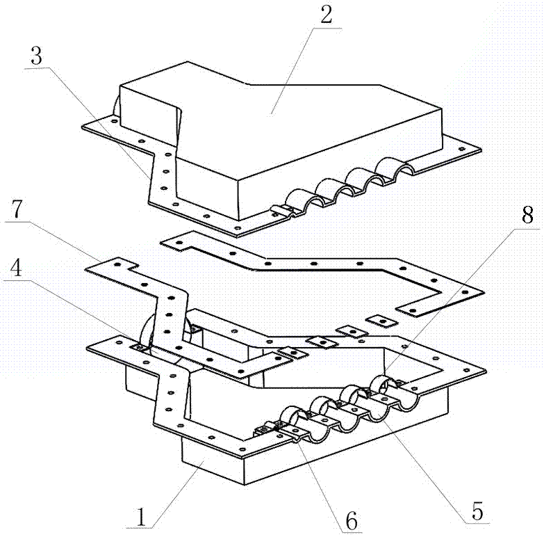
[0025] As shown in the figure, an OPLC terminal peeling, fixing and sealing device of the present invention includes a base 1 and an upper cover 2, and the outer edges of the base 1 and the upper cover 2 are provided with an edge flange 3 extending perpendicular to the side to the outside, and the upper The cover 2 and the base 1 are locked by bolts. One end of the base 1 and the upper cover 2 is provided with a matching OPLC line semicircle groove 4, and the OPLC line semicircle groove 4 of the base 1 and the upper cover 2 is matched up and down to form an OPLC line. Cable hole, the other end of the base 1 and the upper cover 2 is provided with a number of cable outlet semi-circular grooves 5 and a number of optical cable outlet semi-circular grooves 6 that match each other, and the cable outlet semi-circular grooves 5 of the base 1 and the upper cover 2 match up and down correspondingly to form a cable outlet hole , The base 1 and the cable outlet semicircle groove 6 of the u...

Embodiment 2

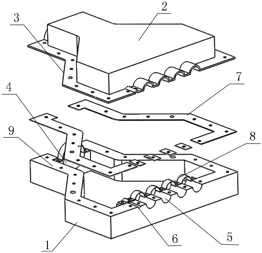
[0035] An OPLC terminal peeling, fixing and sealing device, comprising a base 1 and an upper cover 2, the outer edge of the upper cover 2 is provided with an edge flange 3 perpendicular to the side and extending outward, and the thickness of the side 9 around the base 1 is the same as that of the upper cover 2 edge The width of the flange 3 is matched, and the upper cover 2 and the base 1 are locked by bolts. One end of the base 1 and the upper cover 2 is provided with a matching OPLC cable inlet semicircle groove 4, and the OPLC cable inlet semicircle groove of the base 1 and upper cover 2 4. The upper and lower sides correspond to form the OPLC cable inlet. The base 1 and the other end of the upper cover 2 are provided with a number of cable outlet semi-circular grooves 5 and a number of optical cable outlet semi-circular grooves 6 that match each other. The cable outlet semi-circle grooves 5 of the base 1 and upper cover 2 The upper and lower sides correspond to form the cab...


PUM


Abstract

The invention discloses an OPLC (Optical Power Line Communication) terminal stripping and fixing seal device and a process thereof. The device comprises a base and an upper cover, wherein the upper cover and the base are detachably sealed and fixed; OPLC inlet semicircular grooves matched with one another are formed in one ends of the base and the upper cover; the OPLC inlet semicircular grooves of the base and the upper cover are vertically correspondingly combined to form OPLC inlet holes; a plurality of cable outlet semicircular grooves and a plurality of optical cable outlet semicircular grooves matched with one another are formed in the other ends of the base and the upper cover; the cable outlet semicircular grooves of the base and the upper cover are vertically correspondingly combined to form cable outlet holes; and the optical cable outlet semicircular grooves of the base and the upper cover are vertically correspondingly combined to form optical cable outlet holes. The device disclosed by the invention is convenient to operate and excellent in overall strength, and the OPLC terminal stripping part can be effectively protected.

Description

technical field [0001] The invention relates to a fixed sealing device and a process thereof, in particular to an OPLC terminal stripping fixed sealing device and a process thereof. Background technique [0002] In the construction of traditional residential quarters, strong and weak currents are implemented separately, which results in increased costs for cable laying, management, and maintenance, and repeated construction. In the construction of power optical fiber to the home, cables such as optical fiber composite low-voltage cables (OPLC) are used to lay optical fibers along with low-voltage power lines to achieve meter-to-home. Equipped with passive optical network PON technology, it carries the power distribution and utilization links of the smart grid and related services of "three-network integration". The intelligent photoelectric integrated integrated wiring cabinet undertakes the functions of protection and distribution of electricity and light in the constructi...

Claims


Application Information

Patent Timeline
Patent Type & Authority Applications(China)
IPC IPC(8): G02B6/44G02B6/245
CPCG02B6/245G02B6/4448
Inventor 李惠蓬常家森路浩黄皓宇葛永新谢书鸿
Owner ZTT ELECTRICAL TECH CO LTD
Why Eureka
Try Eureka