DC interline power flow controller

A technology of power flow controller and DC line, applied in the direction of power transmission AC network, AC network with the same frequency from different sources, etc., to achieve the effect of simple circuit structure

Inactive Publication Date: 2017-10-10
CHANGZHOU TIANMAN INTELLIGENT TECH
View PDF3 Cites 2 Cited by
  • Summary
  • Abstract
  • Description
  • Claims
  • Application Information

AI Technical Summary

Problems solved by technology

Since there is no reactive power, reactance and phase angle of AC, the DC transmission system can only adjust the transmission line resistance and DC voltage to control the DC power flow

Method used


Image

  • DC interline power flow controller
  • DC interline power flow controller
  • DC interline power flow controller

Examples


Embodiment Construction

[0021] The technical solutions in the embodiments of the present invention will be described clearly and completely below. Obviously, the described embodiments are only a part of the embodiments of the present invention, rather than all of them. Based on the embodiments of the present invention, all other embodiments obtained by those of ordinary skill in the art without creative work fall within the protection scope of the present invention.

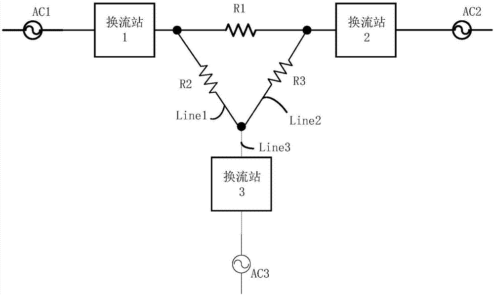
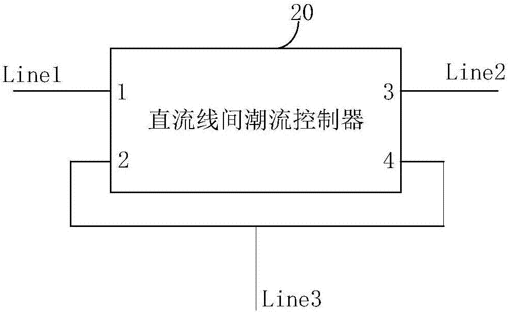
[0022] Such as figure 2 As shown, a DC power flow controller 20 includes a first terminal 1, a second terminal 2, a third terminal 3, and a fourth terminal 4. The first terminal 1 is connected to the first transmission line Line1, and the third terminal 3 is connected to Connect the second transmission line Line2, the second terminal 2 and the fourth terminal 4 are connected in parallel to the third transmission line Line3, and the power flows from the first transmission line Line1 and the second transmission line Line2 to the third transm...


PUM


Abstract

The invention relates to a DC interline power flow controller. The DC interline power flow controller comprises a first terminal, a second terminal, a third terminal and a fourth terminal, wherein the first terminal is connected with a first power transmission line, the third terminal is connected with a second power transmission line, the second terminal and the fourth terminal are connected in parallel and then are connected with a third power transmission line, power flows to the third power transmission line from the first power transmission line and the second power transmission line, the DC interline power flow controller comprises a bidirectional DC / DC converter and a solid-state transformer, the bidirectional DC / DC converter is connected in series with the solid-state transformer, input ends of the bidirectional DC / DC converter are the first terminal and the second terminal, an output end of the bidirectional DC / DC converter is connected with an input end of the solid-state transformer, and output ends of the solid-state transformer are the third terminal and the fourth terminal. By the DC interline power flow controller, DC electric energy flow control can be achieved, the isolation of a circuit is achieved by using the solid-state transformer, and the circuit structure is simple.

Description

Technical field [0001] The invention relates to the technical field of direct current transmission systems, in particular to a direct current power flow controller. Background technique [0002] The multi-terminal DC transmission system is a DC transmission system with 3 or more converter stations connected in series, parallel or hybrid mode. It can realize multi-source power supply and multi-drop point power reception, compared with high-voltage DC transmission at both ends The operation of the system is more economical and flexible, and it is one of the effective technical means to solve the problems of large-scale renewable energy grid connection, large-capacity long-distance power transmission and shortage of power transmission corridors that my country is currently facing. The equivalent circuit of a typical ring network three-terminal DC transmission system is as figure 1 As shown, it is assumed that converter station 1 and converter station 2 are converter stations of two o...

Claims


Application Information

Patent Timeline
Patent Type & Authority Applications(China)
IPC IPC(8): H02J3/36H02J3/06
CPCH02J3/06H02J3/36Y02E60/60
Inventor 曼苏乐
Owner CHANGZHOU TIANMAN INTELLIGENT TECH
Why Eureka
Try Eureka