Minimally invasive positioning tool for laparoscopic surgery and protected supporting and positioning method of tool

A laparoscopic and surgical technology, applied in the field of medical devices, can solve the problems of increasing the difficulty and risk of surgery, difficult to achieve standard operation, and great harm to patients, so as to achieve the effect of providing surgical quality, facilitating standardized operation, and relieving pain

Inactive Publication Date: 2017-10-13
JIAMUSI UNIVERSITY
View PDF8 Cites 6 Cited by
  • Summary
  • Abstract
  • Description
  • Claims
  • Application Information

AI Technical Summary

Problems solved by technology

[0005] The purpose of the present invention is to solve the problem that the existing pneumoperitoneum operation mode of laparoscopic surgery is harmful to the human body and has a large wound, which increases the difficulty and danger of the operation. Other methods of pneumoperitoneum are harmful to the patient and have many complications. Due to the narrow surgical field of view, the cutting of the affected part of the abdominal cavity needs to rely on the experience of doctors, and it is difficult to achieve standardized operations. In order to provide a minimally invasive positioning tool and its protective support positioning method for laparoscopic surgery

Method used


Image

  • Minimally invasive positioning tool for laparoscopic surgery and protected supporting and positioning method of tool
  • Minimally invasive positioning tool for laparoscopic surgery and protected supporting and positioning method of tool
  • Minimally invasive positioning tool for laparoscopic surgery and protected supporting and positioning method of tool

Examples


specific Embodiment approach 1

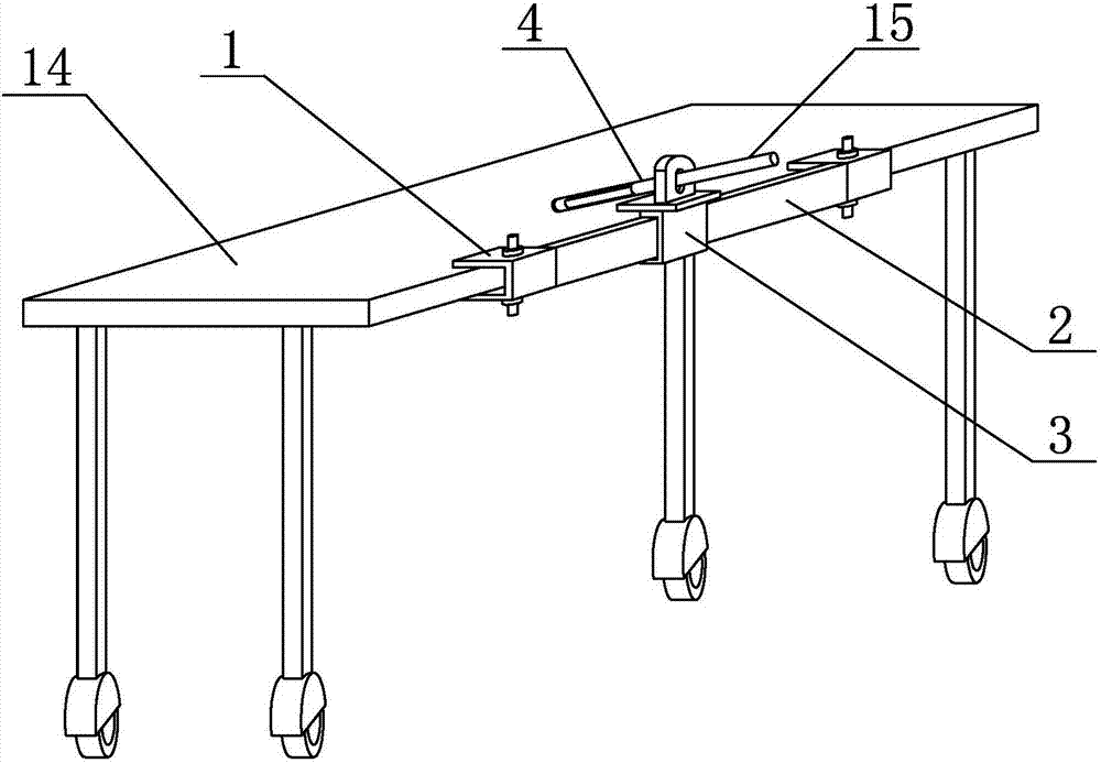
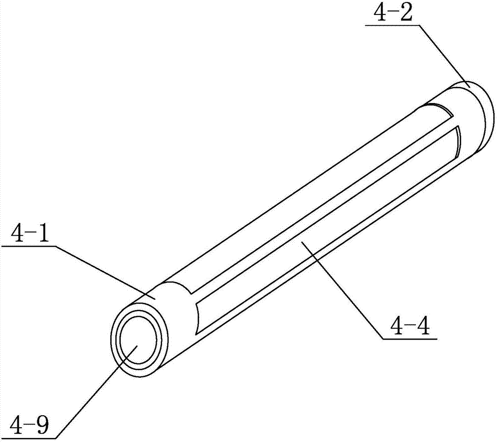
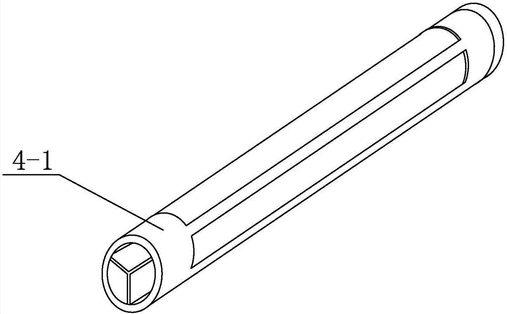
[0046] Specific implementation mode one: combine Figure 1 to Figure 18 Describe this embodiment. This embodiment includes a detachable base 1, a unilateral slideway 2, a movable base 3 and at least one support assembly 4. The detachable base 1 is detachably connected to one side of an operating bed 14. The unilateral slideway 2 is arranged along the length direction of the operating bed 14 and it is connected with the detachable base 1. The movable base 3 is arranged on the unilateral slideway 2 and the two are slidably matched. The movable base 3 is provided with at least A support assembly 4, each support assembly 4 includes a cannula 4-1, a buffer guide head 4-2 and an inflatable bag 4-9, one end of the cannula 4-1 is provided with a buffer guide head 4-2, The other end of the intubation tube 4-1 communicates with the gas source, and the intubation tube 4-1 is processed with a plurality of long holes 4-4, and the inflatable bag 4-9 is arranged in the long holes 4-4 and com...

specific Embodiment approach 2

[0052] Specific implementation mode two: combination Figure 4 to Figure 9 Illustrate the present embodiment, inflatable bag 4-9 comprises a plurality of film capsules 4-3, and a plurality of film capsules 4-3 is arranged side by side, and each film capsule 4-3 communicates with gas source, and film capsule 4-3 3 are provided in one-to-one correspondence with the elongated holes 4-4, and each film capsule 4-3 is arranged toward its corresponding long hole 4-4. When each film capsule 4-3 is in an inflated state, each film capsule 4-3 supports the inner wall 8 of the patient's abdominal cavity through its corresponding long hole 4-4. When each membrane capsule 4-3 is in the deflated state, each membrane capsule 4-3 is in the intubation tube 4-1.

[0053] In this embodiment, the arrangement of a plurality of film capsules 4-3 can effectively divert the air pressure in the airbag 4-9, and can also ensure the smooth effectiveness of the expansion of the airbag 4-9 in the process of...

specific Embodiment approach 3

[0057] Specific implementation mode three: combination Figure 4 , Figure 5 , Figure 7 with Figure 8 Illustrate this embodiment, each inflatable bag 4-9 comprises three film capsules 4-3, and three film capsules 4-3 are middle film capsule 4-3-2 and two end film capsules 4 respectively -3-3, when each membrane capsule 4-3 is inflated, the angle between the two end membrane capsules 4-3-3 is less than or equal to 90°, and the middle membrane capsule 4-3- The included angle between 2 and the end membrane capsule 4-3-3 is less than or equal to 45°.

[0058] The middle film capsule 4-3-2 and the two end film capsules 4-3-3 of this embodiment cooperate with each other to form a triangular support effect on the inner wall 8 of the patient's abdominal cavity, which can match the shape of the inner wall 8 of the patient's abdominal cavity Effectively fit the inner wall 8 of the patient's abdominal cavity, so that the effect of supporting the inner wall 8 of the patient's abdomi...


PUM


Abstract

The invention discloses a minimally invasive positioning tool for a laparoscopic surgery and a protected supporting and positioning method of the tool, and relates to a minimally invasive positioning tool and a minimally invasive surgery method. A pneumoperitoneum operation mode of an existing laparoscopic surgery is very harmful to human bodies and large in wound, surgical difficulty and dangerousness are increased, other pneumoperitoneum modes are very harmful to patients and cause many complications, and standard operation is difficultly realized as an affected part of an abdominal cavity needs to be cut by the aid of experience of a doctor due to a narrow surgical field. A unilateral slide can be connected with a detachable base, a movable base is in sliding fit with the unilateral slide, a supporting component is arranged on the movable base, a buffer type guide head is arranged at one end of an intubation tube, a gas filled bag is arranged inside the intubation tube and communicated with a gas source, and a plurality of slot holes are formed in the intubation tube. The protected supporting and positioning method is characterized in that the gas source is started, gas flow with a gas pressure value P is led into the gas filled bag of the intubation tube, and the gas filled bag is filled with gas to form multi-point supporting or arc-shaped supporting. The minimally invasive positioning tool and the protected supporting and positioning method are used for the laparoscopic surgery.

Description

technical field [0001] The invention relates to a minimally invasive auxiliary tool, which belongs to the technical field of medical devices. Background technique [0002] Laparoscopic minimally invasive surgery, also known as "keyhole" surgery and perforation surgery, is to open a few small holes of about 0.5-1 cm in the abdominal wall of the patient, and use instruments to replace the surgeon's hand through the display of the laparoscope and the TV screen. , into the abdominal cavity to complete the operation. Laparoscopic surgery is a new surgical technique. Compared with traditional surgery, laparoscopic surgery is a type of minimally invasive surgery with small wounds, less trauma, less bleeding, quicker recovery and shorter hospital stay. It is inserted into the abdominal cavity, and the intra-abdominal diseases can be checked, diagnosed and treated through the TV screen, which has less trauma to the patient's body, less interference and faster recovery. Its appearan...

Claims


Application Information

Patent Timeline
Patent Type & Authority Applications(China)
IPC IPC(8): A61B17/00A61B17/32A61G13/10
CPCA61B17/00234A61B17/320016A61B2017/003A61B2017/00544A61G13/10
Inventor 刘英兰王跃生苏德望张立海金凤
Owner JIAMUSI UNIVERSITY
Why Eureka
Try Eureka