Moving coil high frequency booster pump

A booster pump, moving coil technology, applied in engine components, machines/engines, charging systems, etc., can solve the problems of low fuel pressure, complex structure, complex control, etc., and achieve the effect of improving efficiency and fuel pressure.

Active Publication Date: 2022-04-08
NANJING UNIV OF AERONAUTICS & ASTRONAUTICS
View PDF7 Cites 0 Cited by
  • Summary
  • Abstract
  • Description
  • Claims
  • Application Information

AI Technical Summary

Problems solved by technology

The commonly used servo motor single pump has a relatively complex structure, relatively low fuel pressure, and the highest short-circuit fuel pressure does not exceed 8 bar (bar). At the same time, the control of this kind of fuel pump is relatively complicated, so there is an urgent need for a light weight, high pressure, structure. Simple and reliable fuel pump

Method used


Image

  • Moving coil high frequency booster pump
  • Moving coil high frequency booster pump
  • Moving coil high frequency booster pump

Examples


Embodiment Construction

[0017] The present invention will be further described below in conjunction with the accompanying drawings.

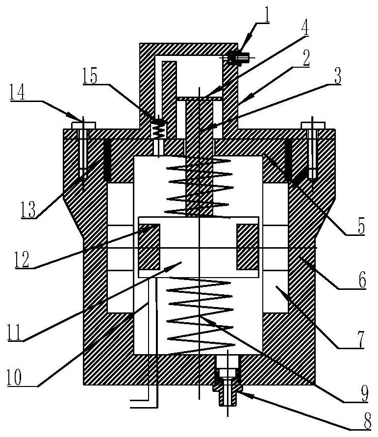
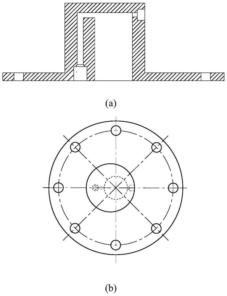
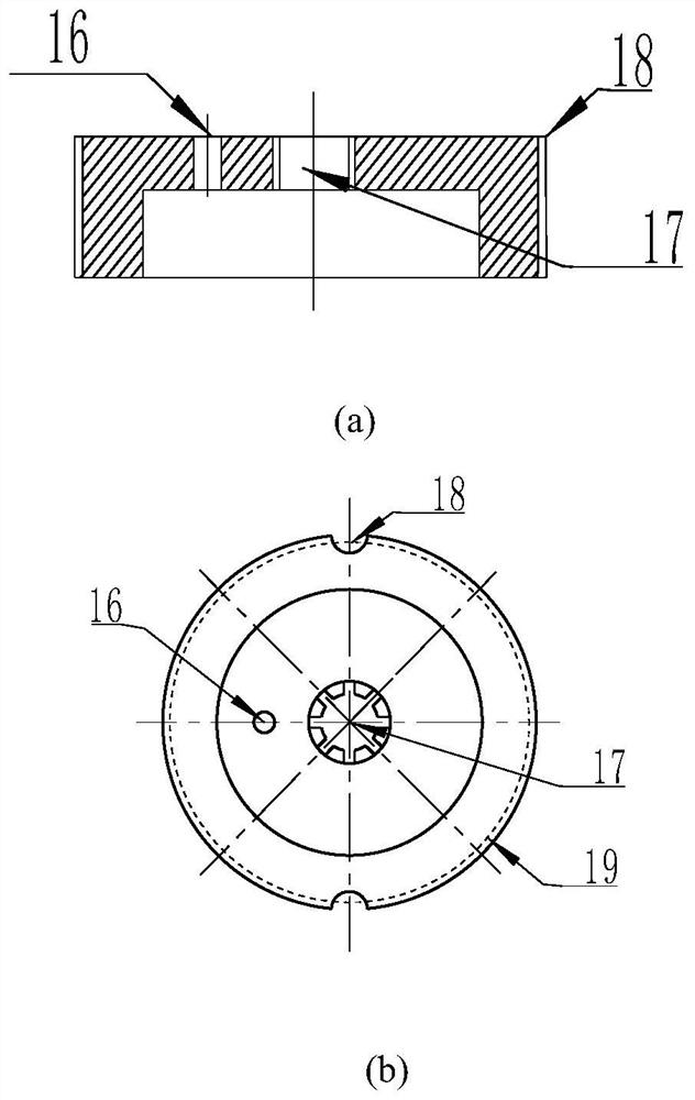
[0018] A moving-coil high-frequency booster pump, comprising an oil inlet 1, an oil cylinder 2, a piston rod 3, a piston 4, a magnetically conductive cover 5, a pump body 6, a permanent magnet 7, an oil outlet 8, a first spring, and a second spring 9. Power line 10, winding frame 11, coil 12, bolts 14, check valve 15, oil return hole 16, the oil cylinder and the pump body are connected by bolts, the magnetically conductive cover 5 is set at the port of the pump body 6, and the guide The magnetic cover and the pump body are connected by threads, image 3 The middle 19 is the middle diameter of the thread, and the oil cylinder is provided with a check valve, an oil inlet 1, a piston and a piston rod 3, and an oil return hole 16 is arranged on the magnetic conductive cover, and the check valve passes through the oil return hole 16 on the magnetic conductive cover. It com...


PUM


Abstract

The present invention proposes a moving-coil high-frequency booster pump, which includes an oil inlet, an oil cylinder, a piston rod, a piston, a magnetically conductive cover, a pump body, a permanent magnet, an oil outlet, a first spring, a second spring, a power cord, Winding frame, coil, bolt, one-way valve, oil return hole, oil cylinder and pump body are connected by bolts, magnetically conductive cover is set at the port of pump body, magnetically conductive cover and pump body are connected by thread, and oil cylinder is provided with One-way valve, oil inlet, piston and piston rod, oil return hole is set on the magnetic conduction cover, the one-way valve communicates with the pump chamber through the oil return hole on the magnetic conduction cover, the first spring is sleeved in the pump chamber On the piston rod, one end of the first spring is connected to the winding frame, one end of the second spring is connected to the winding frame, and the other end is connected to the bottom of the pump body. The permanent magnet is arranged on the inner wall of the pump body, and the coil is wound on the winding frame. The moving-coil high-frequency booster pump of the present invention adopts the linear electromagnetic drive mode, has simple structure, light weight, convenient control, strong driving ability, and can generate higher pressure.

Description

technical field [0001] The invention relates to a fuel boosting machine in an engine, in particular to a moving-coil high-frequency boosting pump. Background technique [0002] The fuel injection system of the engine has a great influence on the performance of the engine. The fuel pressure directly affects the fuel atomization characteristics of the engine. Especially when the aviation two-stroke engine burns medium oil, the atomization is relatively difficult and requires a higher pressure. At the same time, the fuel pump is required to have a relatively simple structure to ensure the power-to-weight ratio and reliability of the engine. The commonly used servo motor single pump has a relatively complex structure, relatively low fuel pressure, and the highest short-circuit fuel pressure does not exceed 8 bar (bar). At the same time, the control of this fuel pump is relatively complicated, so there is an urgent need for a light weight, high pressure, structure. Simple and re...

Claims


Application Information

Patent Timeline
Patent Type & Authority Patents(China)
IPC IPC(8): F02M37/08F02M31/125
CPCF02M31/125F02M37/043F02M37/08
Inventor 周东魏民祥季昊成常诚
Owner NANJING UNIV OF AERONAUTICS & ASTRONAUTICS
Why Eureka
Try Eureka