Measurement point arrangement method for bridge dynamic load tests

A technology of measuring point layout and dynamic load, applied in special data processing applications, instruments, electrical digital data processing, etc., can solve the problems of not picking up signals, unrecognizable deflection modes of bridge horizontal lines, and insufficient representation of signals, etc. To achieve the effect of improving the ability of identification

Active Publication Date: 2017-10-13
GUANGDONG PROVINCIAL ACAD OF BUILDING RES GRP CO LTD
View PDF3 Cites 6 Cited by
  • Summary
  • Abstract
  • Description
  • Claims
  • Application Information

AI Technical Summary

Problems solved by technology

[0007] ⑴ The representativeness of the picked-up signal is insufficient, the quality is not high, and even the signal cannot be picked up because it is arranged at the inflection point of the formation (the vibration signal is zero or very weak)
[0008] ⑵Because the vibration signal pick-up and measurement points are arranged along the longitudinal bridge direction rather than along the bridge plane, some target modes (especially the transverse bridge vibration mode) cannot be identified, resulting in omissions
For example, for a simply supported cast-in-place slab bridge with a relatively large width and span, there will be no targeted arrangement of measuring points, resulting in poor signal quality and unrecognizable bridge deflection mode

Method used


Image

  • Measurement point arrangement method for bridge dynamic load tests
  • Measurement point arrangement method for bridge dynamic load tests
  • Measurement point arrangement method for bridge dynamic load tests

Examples


Embodiment Construction

[0046] The present invention is a kind of measuring point layout method for bridge dynamic load test, specifically comprises the following steps:

[0047] (1) Establish the finite element model of the target structure on the finite element platform:

[0048] In this embodiment, the target structure is a simply supported prefabricated small box bridge with a calculated span of 29.14m and a width of 18.75m. Due to the relatively large width and length of the bridge, the target mode is the first three orders. It is necessary to investigate the lateral deflection mode of the bridge. The finite element model is a plane model. Specifically, Midas / Civil is used to establish the plane model of the bridge.

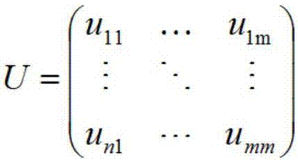
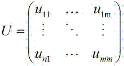
[0049] (2) Extract the target mode shape matrix U according to the finite element model.

[0050] Steps (1) and (2) combine the finite element analysis technology, by establishing the finite element analysis model of the target structure on the computer, to obtain the target mode ...


PUM


Abstract

The invention discloses a measurement point arrangement method for bridge dynamic load tests. The method includes the steps of (1) establishing a finite element model of a target structure on a finite element platform; (2) extracting a target modality vibration-style matrix according to the finite element model; (3) removing unsuitable nodes in the target modality vibration-style matrix, and forming primary freedom degrees; (4) calculating the MAC matrix of two nodes of any combination one by one from the primary freedom degrees; (5) selecting N groups of nodes with the smallest maximum non-diagonal element value; (6) selecting two optimal nodes from the N groups of nodes to enter the measurement of the freedom degrees; (7) selecting one node from the remaining nodes of the primary freedom degrees one by one to enter the measurement of the freedom degrees; (8) obtaining calculating results. The measurement point arrangement method for bridge dynamic load tests combines the finite element analysis technology, is based on the structure dynamic measurement point selection theory, and aims at the target modality of a target bridge to make analysis quick and accurately, and the measurement point arrangement position along the longitudinal or plane distribution of the bridge is obtained; the method is simple and efficient, the collected signals are more representative, and the identification ability of the bridge transverse target modality is improved.

Description

technical field [0001] The invention relates to the field of bridge engineering dynamic performance testing, in particular to a method for arranging measuring points for bridge dynamic load testing. Background technique [0002] Bridge is one of the important transportation facilities. With the development of transportation and the progress of science and technology, bridge inspection has been paid more and more attention, and dynamic load test is an important part of bridge inspection. The target bridge will vibrate under external excitation, and the modal parameters of the bridge itself can be identified by picking up the vibration signal, and then the working performance of the bridge can be evaluated. Bridge dynamics is an important topic in the development of modern bridges. On the one hand, it can more truly reveal the dynamic force and deformation nature of the bridge structure under the action of vehicle loads, and on the other hand, it can describe the nature of th...

Claims


Application Information

Patent Timeline
Patent Type & Authority Applications(China)
IPC IPC(8): G06F17/50
CPCG06F30/13G06F30/23
Inventor 李君李健邓军孙晖吴迪李冠军章恒
Owner GUANGDONG PROVINCIAL ACAD OF BUILDING RES GRP CO LTD
Why Eureka
Try Eureka