
Dry powder stirrer

A technology for mixers and stirring motors, which is applied to mixer accessories, mixers with rotating stirring devices, mixers, etc. It can solve the problems of long time consumption, low mixing uniformity, and affecting the workshop environment, so as to improve the mixing effect. Effect of shortening mixing time and improving production efficiency

Pending Publication Date: 2017-10-17
江西省浩燃冶金设备有限责任公司
View PDF5 Cites 6 Cited by
  • Summary
  • Abstract
  • Description
  • Claims
  • Application Information

AI Technical Summary

Problems solved by technology

[0002] Dry powder mixing is widely used in the chemical industry. In order to obtain a uniform mixture, manpower has been difficult to meet the technical requirements. Therefore, the application of mixers has a long history, from the earliest manpower to the later water and wind. There are higher and higher requirements on the speed and stability of stirring. Electricity is generally used to drive stirring now. Due to the characteristics of lightness and dispersion of dry powder, a large amount of dust is likely to be generated during the process of conveying and stirring, which is very harmful to the workers and the factory environment. Great harm, the existing mixers seldom pay attention to this part, and the sealing and dust removal measures of the mixer are not done well enough, which causes great harm to the health of workers, and the environment of the dry powder mixing workshop is harsh
[0003] The current dry powder mixer generally uses a single propeller to stir, and the single propeller takes a long time to stir, the stirring uniformity is not high, the stirring efficiency is low, and there is a problem that the dry powder is not discharged smoothly; in addition, because various raw materials are powder , stirring and mixing is full of dust, which affects the workshop environment and seriously affects the physical and mental health of workers

Method used


Image

  • Dry powder stirrer
  • Dry powder stirrer

Examples


Embodiment Construction

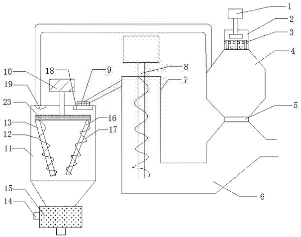
[0015] see figure 1 , figure 1 It is a schematic structural view of the present invention, a dry powder mixer, comprising a stirring container 11 and a blower fan 1, a stirring motor 10 is arranged above the stirring container 11, a camera 19 is arranged inside the stirring container 11, and a There is a transmission arm 23, the top of the transmission arm 23 is fixedly installed with the stirring motor 10, and the bottom is connected with the first screw shaft 13 and the second screw shaft 16, and the first screw shaft 13 and the second screw shaft 16 are installed symmetrically, The top of the transmission arm 23 is also provided with a vibrating screen 18, the vibrating screen 18 is detachable, the mixing container 11 is provided with a feed inlet 9, and the first screw shaft 13 is equipped with a first screw blade 12 on the surface, so A second helical blade 17 is installed on the surface of the second screw shaft 16, a powder outlet box 15 is arranged below the stirring ...


PUM


Abstract

A dry powder stirrer comprises a stirring container and a fan. A stirring motor is arranged above the stirring container which is provided with a feeding port, a transmission arm is arranged in the stirring container, the stirring motor is fixedly mounted above the transmission arm, a first spiral shaft and a second spiral shaft are connected below the transmission arm, a powder outgoing box is arranged below the stirring container, an electric control device is arranged on the left side of the powder outgoing box, a powder conveying pipe is arranged on the right side of the stirring container and communicated with a powder conveying groove, a filtering cavity is arranged below the fan, and a filtering cover is arranged below the filtering cavity. The dry powder stirrer can uniformly scatter a material into a stirring barrel, thereby being good in mixing effect; through a display screen and a timing device, energy can be saved effectively, production efficiency can be improved, and the dry powder stirrer is worthy of vigorous popularization.

Description

technical field [0001] The invention belongs to the technical field of mixers, and in particular relates to a dry powder mixer. Background technique [0002] Dry powder mixing is widely used in the chemical industry. In order to obtain a uniform mixture, manpower has been difficult to meet the technical requirements. Therefore, the application of mixers has a long history, from the earliest manpower to the later water and wind. There are higher and higher requirements on the speed and stability of stirring. Electricity is generally used to drive stirring now. Due to the characteristics of lightness and dispersion of dry powder, a large amount of dust is likely to be generated during the process of conveying and stirring, which is very harmful to the workers and the factory environment. The existing mixers seldom pay attention to this part, and the sealing and dust removal measures of the mixers are not done well enough, which causes great harm to the health of workers, and t...

Claims


Application Information

Patent Timeline
IPC IPC(8): B01F7/08B01F15/02B01F15/00B01F3/20B01F3/18B01D46/00B01D50/00B01F23/70
CPCB01D46/00B01F23/69B01F23/713B01F27/721B01F35/188B01F35/187B01F35/71B01F35/7175B01D50/20
Inventor 赖平连
Owner 江西省浩燃冶金设备有限责任公司
Features
  • Generate Ideas
  • Intellectual Property
  • Life Sciences
  • Materials
  • Tech Scout
  • Unparalleled Data Quality
  • Higher Quality Content
  • 60% Fewer Hallucinations
Learn More